The AF
OUT signals from the VOL1
line are also amplified
at
the AF
amplifier (LOGIC unit
02)
to
output AF signal
from the
microphone
connector.
3-1-5
SQUELCH
CIRCUIT
(MAIN
and LOGIC
UNITS)
A
squelch circuit cuts out
AF signals
when no RF signals
are
being received.
By detecting noise
components
in the AF
signals, the
squelch circuit turns
the AF mute
switch OFF.
A portion of
the AF signals from the FM
IF
1C
(IC4 pin
9)
are applied to
the active filter
(104
pin
10)
through the
noise
filter
(0145
—
0147,
R128).
The active filter
section
in 104
amplifies noise components
of frequency of 20
kHz
and above,
and are rectified at the noise
detector (D26)
and then
triggers the noise switch
(Q45).
3-2-3
DRIVE/POWER
AMPLIFIER CIRCUITS
(MAIN UNIT)
The
signal from the
modulation circuit is passed through
the
transmit/receive switching
circuit (D2) and amplified
at the
pre-driver (Oil),
driver
(012),
and the
power
module
(102)
in sequence to
obtain
50
W*
(at
13.8 V DC) of RF
power.
*
10 W for the IC-2000
Thailand version.
The
amplified signal is passed
through the antenna
switching circuit (D7), ARC
detector circuit (L10,
D8,
D9),
and low-pass
filter (L11, LI
2,
061,
062)
and is then
applied to
the antenna
connector.
The
collector
current of the
driver
(012)
are controlled
by
the ARC
circuit to
protect the
power module from
a
mismatched condition as
well as to
stabilize the
output
power.
The
noise switch
(045)
converts the
rectified signals to
a
“High”
or “Low" signal and
applied this to the
CRU
(LOGIC
unit
102
pin
5)
as the
busy signal.
When the
CRU
receives “High,” the CRU
outputs the
mute signal
through the
Data expander 1C
(MAIN unit IC9,
pin
11)
to
cut the AF
signals at the
detector mute switch
(037).
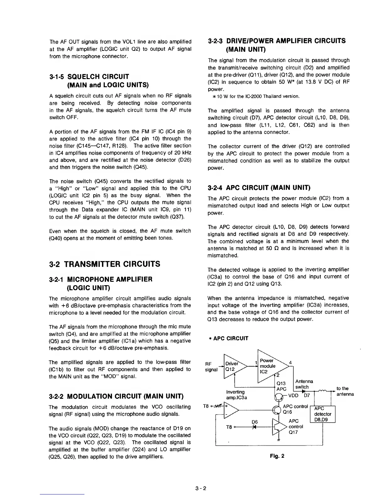
3-2-4
APC CIRCUIT
(MAIN UNIT)
The ARC
circuit protects
the power module
(IC2) from
a
mismatched
output load
and selects High
or Low
output
power.
Even when
the squelch is
closed, the AF
mute switch
(040)
opens at
the moment of
emitting been tones.
3-2
TRANSMITTER
CIRCUITS
3-2-1
MICROPHONE
AMPLIFIER
(LOGIC UNIT)
The ARC detector
circuit (L10,
D8, D9) detects
forward
signals and
rectified signals at D8
and D9 respectively.
The combined voltage is at
a minimum
level when the
antenna is
matched at 50 O
and is increased
when it
is
mismatched.
The detected
voltage is
applied to the
inverting amplifier
(IC3a)
to
control the base
of 016
and input current of
IC2
(pin
2)
and 012 using
013.
The
microphone
amplifier circuit
amplifies audio signals
with
-F6 dB/octave
pre-emphasis
characteristics from
the
microphone
to
a level needed
for the
modulation circuit.
The AF signals
from the
microphone through the
mic mute
switch
(04),
and are amplified at
the
microphone amplifier
(05)
and the
limiter amplifier (IC1 a)
which has a
negative
feedback
circuit for
-1-6
dB/octave
pre-emphasis.
The
amplified
signals are applied to
the low-pass
filter
(ICIb) to
filter
out
RF components
and then applied to
the
MAIN unit as the
“MOD” signal.
3-2-2
MODULATION
CIRCUIT (MAIN UNIT)
The
modulation circuit
modulates the VCO
oscillating
signal
(RF signal) using
the microphone
audio signals.
The audio
signals (MOD) change
the reactance of D19
on
the
VCO circuit
(022,
023,
D19) to
modulate the oscillated
signal at
the VCO
(022,
023).
The
oscillated signal is
amplified at
the
buffer amplifier
(024)
and LO
amplifier
(025, 026),
then
applied
to
the drive
amplifiers.
When the
antenna
impedance is
mismatched, negative
input
voltage of the
inverting
amplifier (IC3a) increases,
and the base
voltage
of
016
and the
collector current of
013
decreases to reduce
the output
power.
•
APC
CIRCUIT
3-2