SECTION 6 TROUBLESHOOTING
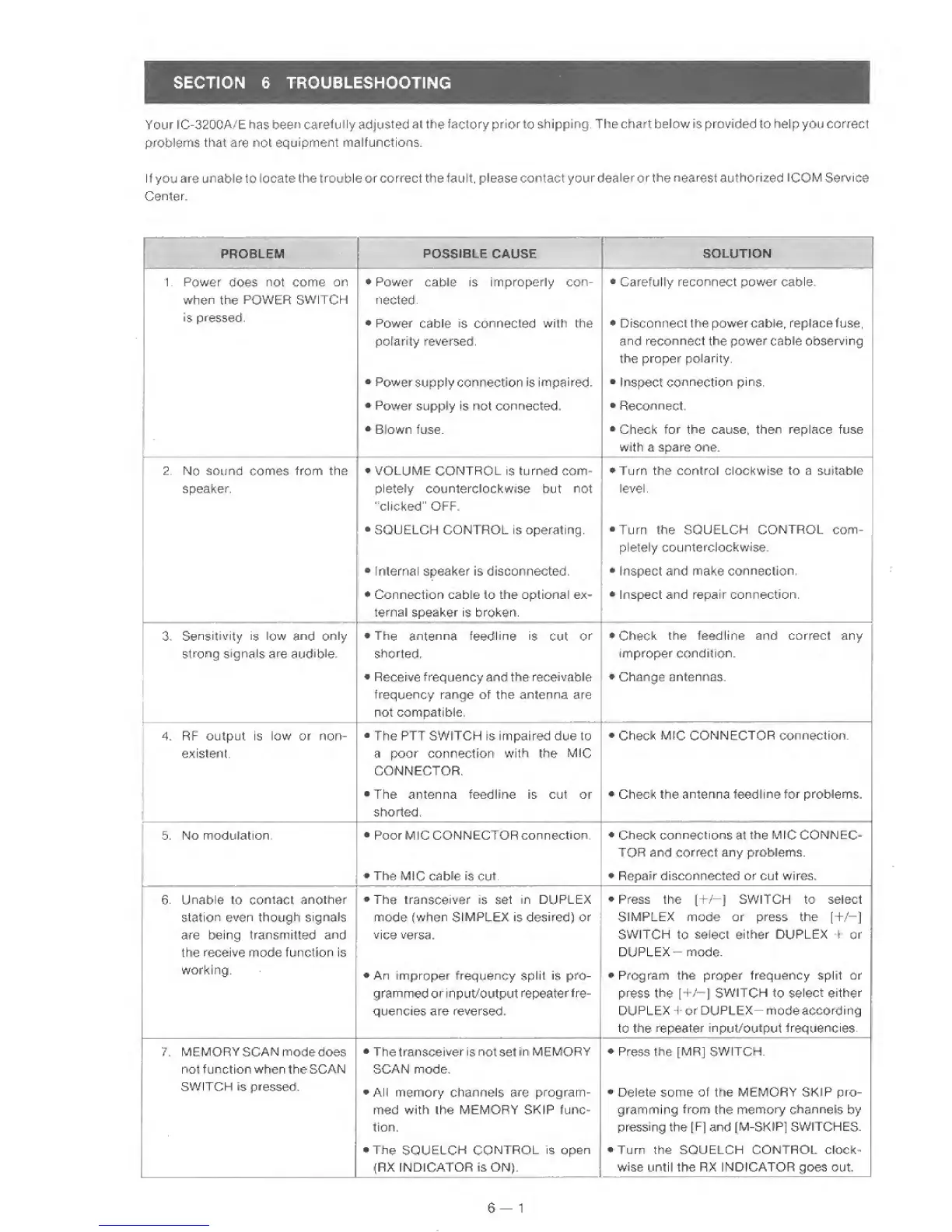
Your I C-320CA/E has
been
carefu
lly
adjusted
at
the
factory
prior
to
shipping. The chart below is provided to hel
p
you correct
problems that are
not
equipment malfunctions.
If
you
are unable
to locate the trouble or correct the fault, please
contactyourdealerorthe nearest authorized
ICOM Service
Center.
PROBLEM
POSSIBLE
CAUSE
SOLUTION
1. Power does not come on
•
Power cable is improperly con-
•
Carefully reconnect power cable.
1
when
the
POWER SWITCH
n
acted.
!
IS
pressed.
1
*
Power
cable
is conrrecied
with
the
•
Disconnect
the powercable, replace fuse,
i
polarity reversed.
and reconnect the power
cable
observing
the proper
polarity.
•
Power
supply connection is
impaired.
*
Inspect
connection
pins
•
Power
supply is
not
connected.
•
Reconnect,
*
Blown fuse.
*
Check
for
the cause,
then
replace fuse
with a spare one.
2.
No
sound corrres from the
•
VOLUME CONTROL
is turned com-
•
Turn the control clockwise to a suitable
speaker.
pletely
counterclockwise but
not
"clicked" OFF.
level.
•
SQUELCH CONTROL is operating. •Turn the SQUELCH
CONTROL
com-
pletefy
counterclockwise.
»
fnlernal speaker is disconnected.
•
Inspect and make
connection.
*
Connectron cable
to
the optional ex-
•
Inspect and repair connection.
ternaf
speaker is broken.
3,
Sensitivity is
low
and
only
•
The antenna
feedline is
Cut
or
•
Check
the feedJine and correct any
strong signals are audible. shorted.
improper
condition.
•
Receive frequency and the receivable
•
Change antennas.
frequency
range of the
antenna
are
not compatible,
1
1
1
4. RF output is low or non-
•
The PTT SWITCH is impaired due to
•
Check
MIC CONNECTOR connection.
existent. a poor connection
with
the
MJC
CONNECTOR.
•
The antenna feedline is cut or
•
Check the antenna teedline
for
problems.
shorted.
5. No modulation.
•
Poor MIG CONNECTOR
connection.
•
Check
connections
at
the
M
fC CONN EC-
TOR and correct
any problems.
•
The MJC
cable is cut.
•
Repair disconnected or cut wires.
6. Unable
to
contact
another
•
The transceiver
is set
in DUPLEX
•
Press the
1+/—)
SWITCH to select
station even
though
signals
mode
(when
SIMPLEX is desired) or
SIMPLEX mode
or
press the
[+/-J
are
being transmitted
and
vice versa.
SWITCH
to
select either
DUPLEX t
or
the
receive
mode function is
DUPLEX-
mode.
working.
•
An
improper frequency
split
is
pro-
•
Program the proper frequency split or
grammed
or input/output
repeater
fre-
press the [+/—]
SWITCH
to
select either
quencies are
reversed.
DUPLEX 1 or
DUPLEX
mode
according
to
the repeater input/output frequencies.
7.
MEMORY SCAN
modedoes
•
The
transceiver
is
not set
in
MEMORY
•
Press
the
[MR] SWITCH.
not
function
when the SCAM
SCAN
mode.
SWITCH
is
pressed.
•
AN
memory
channels arc program-
•
Delete some of the MEMORY SKIP pro-
med with the MEMORY SKIP func- gramming
frorn
the
memory channels
by
tion. pressing the
[Ff
and
fM-SKIP]
SWITCHES,
•
The
SQUELCH
CONTROL
is open
•
Turn the SQUELCH CONTROL clock-
(RX fNDiCATOR is ON). wise until the RX INDICATOR goes out.
6
—
1
 Loading...