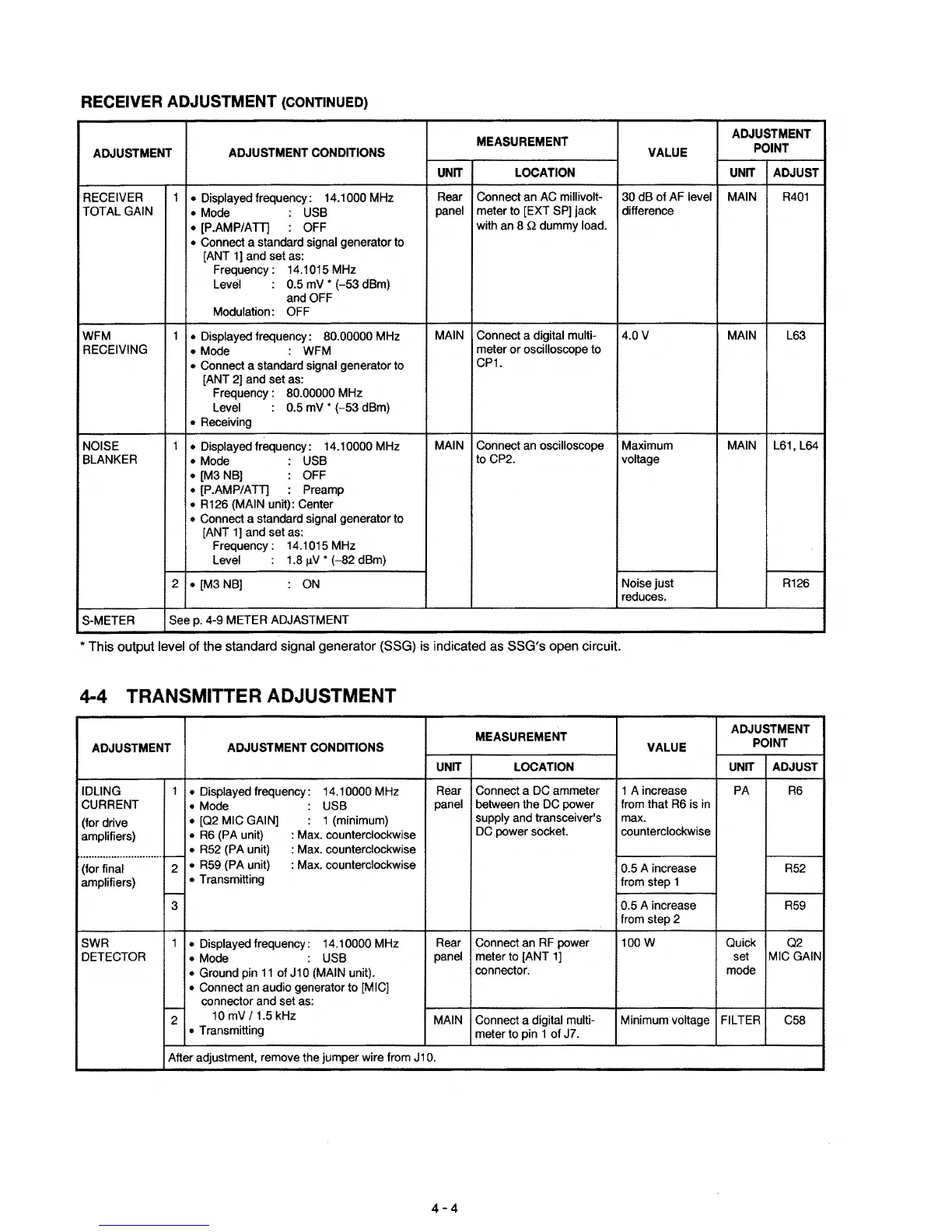
RECEIVER
ADJUSTMENT
(CONTINUED)
MEASUREMENT
ADJUSTMENT
ADJUSTMENT
ADJUSTMENT
CONDITIONS
VALUE
POINT
UNIT
LOCATION
UNIT
ADJUST
RECEIVER 1
• Displayed frequency:
14.1000 MHz
Rear Connect an AC millivolt- 30
dB
of
AF level MAIN
R401
TOTAL GAIN
• Mode
USB
panel
meter to [EXT
SPJ
jack
difference
• [P.AMP/ATT)
OFF
with an 8
Q dummy load.
• Connect a standard signal generator to
[ANT
1J
and set as:
Frequency: 14.1015 MHz
Level
0.5 mV •
(-53
dBm)
and OFF
Modulation: OFF
WFM
1
• Displayed frequency:
80.00000 MHz
MAIN
Connect a digital multi-
4.0V
MAIN L63
RECEIVING
• Mode
: WFM
meter
or
oscilloscope to
• Connect a standard signal generator to
CP1.
[ANT 2] and set as:
Frequency: 80.00000 MHz
Level
0.5 mV •
(-53
dBm)
• Receiving
NOISE
1
• Displayed frequency:
14.10000 MHz
MAIN
Connect an oscilloscope
Maximum MAIN
L61.L64
BLANKER
• Mode
:
USB
to CP2. voltage
•
[M3NB]
: OFF
• [P.AMP/ATT)
:
Preamp
• R126 (MAIN unit): Center
• Connect a standard signal generator to
[ANT lJ and set as:
Frequency: 14.1015 MHz
Level
:
1.8 ltV •
(-82
dBm)
~3NB]
ON
Noise just
R126
reduces.
S-METER
See
p.
4-9 METER ADJASTMENT
• This output level of the standard signal generator (SSG) is indicated as SSG's open circuit.
4-4 TRANSMITTER ADJUSTMENT
MEASUREMENT
ADJUSTMENT
ADJUSTMENT
ADJUSTMENT
CONDITIONS
VALUE
POINT
UNIT
LOCATION
UNIT
ADJUST
IDLING
1
• Displayed frequency:
14.10000 MHz
Rear Connect a DC ammeter 1 A increase PA
R6
CURRENT
• Mode
USB
panel
between the DC power
from that R6 is in
(for drive
• [Q2 MIC GAIN]
: 1 (minimum)
supply and transceiver's max.
amplifiers)
•
R6
(PA unit)
: Max. counterclockwise
DC power socket. counterclockwise
uu
..........
•••••••••••••••
I--
• R52 (PA unit)
: Max. counterclockwise
(for final
2
• R59 (PA unit)
: Max. counterclockwise
0.5 A increase
R52
amplifiers)
• Transmitting
from step 1
I--
3
0.5 A increase
R59
from step 2
SWR
1
• Displayed frequency:
14.10000 MHz
Rear
Connect an RF power
l00W
Quick Q2
DETECTOR
• Mode
USB
panel
meter to [ANT
1]
set
MICGAIN
• Ground pin
11
of
Jl0
(MAIN unit).
connector. mode
• Connect an audio generator to [MIC]
-
connector and set as:
2
10 mV
/1.5
kHz
MAIN Connect a digital multi- Minimum voltage FILTER
C58
• Transmitting
meter to pin 1 of J7.
After adjustment, remove the jumper wire from
J10.
4-4

 Loading...


