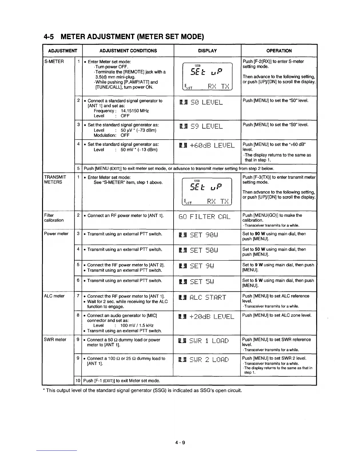
4-5 METER ADJUSTMENT (METER SET MODE)
ADJUSTMENT
ADJUSTMENT
CONDITIONS
DISPLAY
OPERATION
S-METER
1
• Enter Meter set mode:
Push [F-2(RX)) to enter S-meter
.Turn power OFF.
USB
setting mode.
.Terminate the [REMOTE) jack with a
CC
,_
L' P
_'L
L
3.5(d) mm mini-plug.
Then advance to the following setting,
·While pushing [P.AMP/ATT] and
E
I:;:~
>::
or::·::
or push [UP)/[DN) to scroll the display.
[TUNE/CALL), turn power ON.
:·:IT
2
• Connect a standard signal generator to
gill
~:;O
I [:'I![:'1
Push [MENU) to set the
"SO"
level.
[ANT
1]
and set as:
1!b
••
dB
L_. L
•••
'.'
L
••
I
••
Frequency: 14.15150 MHz
Level OFF
3
• Set the standard signal generator as:
IJII
~::;I:~
L..EI')FL
Push [MENU) to set the "S9" level.
Level 50
flV *
(-73
dBm)
Modulation: OFF
4
• Set the standard signal generator
as~
1.111
·+·i::::i;:jc1f.:::
L..
E:
I.)
i:::
L.
Push [MENU] to set the "+60 dB"
Level
50 mV *
(-13
dBm)
level.
·The display returns to the same as
that in step
1.
5 Push [MENU (EXITJ) to exit meter set mode,
or
advance to transmit meter setting from step 2 below.
TRANSMIT
1
• Enter Meter set mode:
Push [F-3(TX)] to enter transmit meter
METERS
See "S-METER" item, step 1 above.
USB
setting mode.
CC
,_
L'P
_'L
L
Then advance to the following setting,
,.
r'II
..
1
'1'::<
or push [UP)/[DN) to scroll the display.
I:
:·:!1
."1:
.•
0
"1
..............................
Filter
2
• Connect an
RF
power meter to [ANT 1].
(:,()
F'
I
i...."r
E:
F;:~
r:~:~l
Push [MENU(GOl) to make the
calibration calibration.
·Transceiver transmits for a while.
..............................
Power meter 3
• Transmit using
an
external PTT switch.
ii.ll1
~:=;E::
'r
')Oi.
.
.1
Set to 90 W using main dial, then
push [MENU).
4
• Transmit using an external
PIT
switch.
IJi
~::;E:"r
::::il;:j
i..,1
Set to 50 W using main dial, then
push [MENU).
5
• Connect the
RF
power meter to [ANT 2].
111m
~::;E~T'
·)i
..
.1
Set to 9 W using main dial, then push
• Transmit using an external PTT switch.
[MENU].
6
• Transmit using an external PTT switch.
mUll
~::;E:·T
I:::';
I
Set to 5 W using main dial, then push
..... 1....
[MENU).
..............................
ALC meter
7
• Connect the
RF
power meter to [ANT 1].
1(111
f~L.C:
~::;
-r
f~
F:
or
Push [MENU] to set ALC reference
• Wait for 2 sec. while receiving for the ALC
level.
function to engage.
·Transceiver transmits for a while.
8
• Connect an audio generator to [MIG]
II
III
+.
:;;~
i;:J
(j
E:
i....E:i.)E:L.
Push [MENU] to set ALC zone level.
connector and set as:
1111
••
1111
Level 100 mV
/1.5
kHz
• Transmit using an external
PIT
switch.
..............................
SWR meter 9
• Connect a 50
Q dummy load or power
li.Jil
~::;
t.J
i:~~
1.
1....
C)
r~
[)
Push [MENU] to set SWR reference
meter to [ANT 1].
level.
·Transceiver transmits for a while.
9
• Connect a 100
Q
or
25 Q dummy load to
II!
!!D
~:::;
1.1.l1:;~:
~~~
L..e)
rll)
Push [MENU] to set SWR 2 level.
[ANT 1].
1III
••
dB
·Transceiver transmits for a while.
·The display returns to the same as that in
step
1.
10
Push
[F-1
(EXIT)] to exit Meter set mode.
*
This
output
level
of
the
standard
signal
generator
(SSG)
is
indicated
as
SSG's
open
circuit.
4-9

 Loading...


