TRANSMITTER ADJUSTMENT (CONTINUED)
MEASUREMENT
ADJUSTMENT
ADJUSTMENT
ADJUSTMENT
CONDITIONS
VALUE
POINT
UNIT
LOCATION
UNIT
ADJUST
AM
1
• Displayed frequency:
14.10000 MHz
MAIN Connect an oscilloscope 200 mVp-p MAIN R195
MODULATION
• Mode
AM
to CP5.
•
[01
RF
POWER)
H
• [02 MIC GAIN)
5
• Disconnect the plug from J4 (MAIN unit).
2
• Connect the plug to J4 (MAIN unit).
Rear
Connect an RF power
35W
R499
• Apply no signal to [MIG] connector.
panel
meter to [ANT
1)
• Transmitting
connector.
3
• Connect an audio generator to [MIG]
Connect a modulation 85% modulation
R271
connector and set as:
analyzer to [ANT1) via an
100 mV
/1
kHz
attenuator.
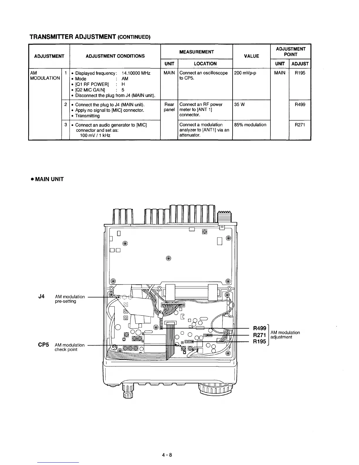
-MAIN
UNIT
o
®
DD
J4
AM
modulation
---4l-!~~;;F':+l'I---L/
pre-setting
CPS
AM
modulation
---U-II-\.\~--===,........j===
check point
4-8
R499]
R271
A~
modulation
adjustment
R19S

 Loading...


