The filtered or bypassed signals are applied to the buffer
amplifier (065), IF amplifiers (042,
043)
and buffer ampli-
fier (044) to obtain a detectable level. The
AGC
voltage is
supplied to the 2nd gate of
042
for
AGC
operation.
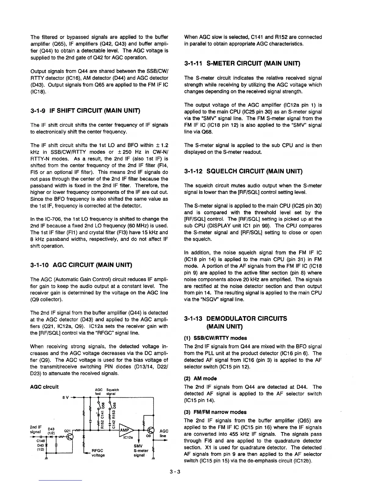
When AGC slow is selected,
C141
and R152 are connected
in
parallel to obtain appropriate AGC characteristics.
3-1-11 S-METER CIRCUIT (MAIN UNIT)
Output signals from
044
are shared between the SSB/CW/
RTTY detector (IC16),
AM
detector (044) and AGC detector
(043). Output signals from
065
are applied to the
FM
IF
IC
(IC18).
The S-meter circuit indicates the relative received signal
strength while receiving by utilizing the
AGC
voltage which
changes depending
on
the received signal strength.
3-1-9 IF SHIFT CIRCUIT (MAIN UNIT)
The IF shift circuit shifts the center frequency of IF signals
to electronically shift the center frequency.
The output voltage of the AGC amplifier (IC12a pin 1) is
applied to the main
CPU
(IC25 pin 30) as
an
S-meter signal
via the "SMV" signal line. The
FM
S-meter signal from the
FM
IF
IC
(IC18
pin
12)
is
also applied to the "SMV" signal
line via 068.
The IF shift circuit shifts the 1st
LO
and BFO within ± 1.2
kHz
in
SSB/CW/RTTY modes or ± 250
Hz
in
CW-N/
RTTY-N modes. As a result, the 2nd IF (also 1st IF) is
shifted from the center frequency of the 2nd IF filter
(F14,
Fl5 or
an
optional IF filter). This means
2nd
IF signals
do
not pass through the center of the 2nd IF filter because the
passband width is fixed
in
the 2nd IF filter. Therefore, the
higher or lower frequency components of the IF are cut out.
Since the BFO frequency is also shifted the same value as
the 1
st
IF,
frequency
is
corrected at the detector.
In
the IC-706, the 1st
LO
frequency is shifted to change the
2nd IF because a fixed 2nd
LO
frequency (60 MHz) is used.
The 1st IF filter (FI1) and crystal filter
(F13)
have 15 kHz and
8 kHz passband widths, respectively, and do not affect IF
shift operation.
The S-meter signal is applied to the sub CPU and is then
displayed
on
the S-meter readout.
3-1·12 SQUELCH CIRCUIT (MAIN UNIT)
The squelch circuit mutes audio output when the S-meter
signal is lower than the [RF/SOL] control setting level.
The S-meter signal
is
applied to the main
CPU
(IC25 pin
30)
and
is compared with the threshold level set
by
the
[RF/SOL] control. The [RF/SOL] setting is picked
up
at the
sub
CPU
(OISPLAY unit
IC1
pin 99). The
CPU
compares
the S-meter signal and [RF/SOL] setting to close or open
the squelch.
3-1-10 AGC CIRCUIT (MAIN UNIT)
The
AGC
(Automatic Gain Control) circuit reduces IF ampli-
fier gain to keep the audio output at a constant level. The
receiver gain is determined by the voltage
on
the
AGC
line
(09
collector).
In
addition, the noise squelch signal from the
FM
IF IC
(IC18 pin 14)
is applied to the main CPU (pin 31)
in
FM
mode. A portion of the AF signals from the
FM
IF
IC
(IC18
pin
9)
are applied to the active filter section (pin 8) where
noise components above 20 kHz are amplified. The signals
are rectified at the noise detector section and then output
from pin 14. The resulting signal is applied to the main
CPU
via the "NSOV" signal line.
The 2nd IF signal from the buffer amplifier (044) is detected
at
the AGC detector (043) and applied to the
AGC
ampli-
fiers (021, IC12a,
09).
IC12a sets the receiver gain with
the [RF/SOL] control via the "RFGC" signal line.
When receiving strong signals, the detected voltage in-
creases and the
AGC
voltage decreases via the
OC
ampli-
fier (09). The
AGC
voltage
is
used for the bias voltage of
the transmiVreceive switching
PIN
diodes (013/14,
0221
023) to attenuate the received signals.
3·1-13 DEMODULATOR CIRCUITS
(MAIN UNIT)
(1) SSB/CW/RTTY modes
The 2nd IF signals from
044
are mixed with the BFO signal
from the PLL unit at the product detector (IC16 pin 6). The
detected AF signal from IC16 (pin
3)
is applied to the AF
selector switch (IC15 pin 12).
(2)
AMmode
The 2nd IF signals from
044
are detected at 044. The
detected AF signal is applied to the
AF
selector switch
(IC15
pin
14).
(3)
FM/FM
narrow modes
The 2nd IF signals from the buffer amplifier (065) are
applied to the
FM
IF
IC
(IC15 pin 16) where the IF signals
are converted into 455 kHz IF signals. The signals pass
through FI6 and are applied to the quadrature detector
section.
X1
is used for quadrature detector. The detected
AF signals from pin 9 are then applied to the AF selector
switch (IC15 pin 15) via the de-emphasis circuit (IC12b).
SMV
S-meter
signal
8
+
:;;
o
:;l
a:
AGe Squelch
fast
signal
RFGC
voltage
021 ,...,.........
----+---1
8 V
---1
.......---<...----...-------,
AGCclrcult
2nd IF
043
signal
(112)
----.
.......
......-ft-oMHf::}
C148
043
(112)
+--+----'
3-3

 Loading...


