TIPS FOR THE USB PORT SETTINGS
8
3-1 How to check the internal circuit for each COM port
You can check the corresponding internal circuit, USB 1 or USB 2, for each COM port in the Device Manager.
(1) Open the Device Manager screen.
• To display the Device Manager screen with Microsoft
®
Windows
®
7 do the steps below.
- The description may differ according to your OS version or settings. Refer to your PC’s instruction
manual, or help file for details.
1) Click “Start menu” and then “Control Panel.”
2) Click “Hardware and Sound.”
3) Click “Device Manager” in “Device and Printer” group.
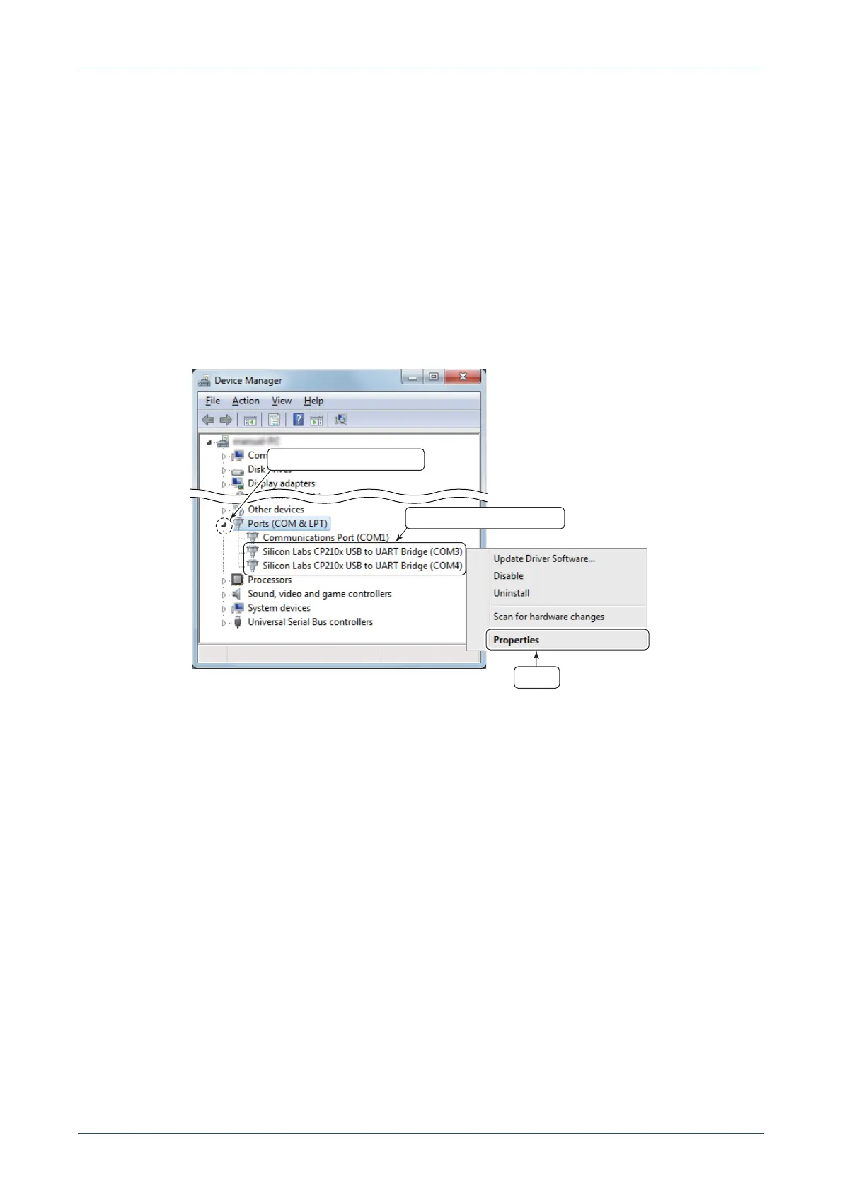
• Click the triangle mark for “Ports (COM & LPT)” to display the contents.
(2) Right-click the COM port that you want to check the internal circuit, and select “Properties.”
• The “Silicon Labs CP210x USB to UART Bridge (COM✱) Properties” screen is displayed.
✱ is the COM port number
Right click the port to confirm
Click
Click to display the contents

 Loading...


