3. CH
ECKING
THE
OP
ERATION
(1)
While
performing the installation, set the marker switch
of the unit
to
the
"OFF"
position and the marker fre-
quency switch
in
the "100KHz" position_
(2)
Connect the plug of the internal speaker on the top
cover
to
the original connector, or an external speaker
to
the external speaker jack on the rear panel.
(3)
Make
sure
the
power switch
of
your
1C-730
is
turned
OFF. Set the other controls and switches
in
the receive
mode according
to
the manual
of
IC·730. Then connect
the power plug
to
the
power socket
of
the
IC
-730.
(4)
Turn the power switch of the IC-730
ON,
and the set
operates
in
the
receive mode.
(5)
Set the marker switch of this unit to the
"ON"
position
and the marker frequency switch
in
the " 100KHz"
position. Then turn the tuning control knob, and you
can receive a strong signal on
every 100KHz.
(6)
Set the marker frequency switch
in
the "25KHz"
po
.
sition, and you can also receive a strong signal on every
25KHz. These are the complete operations
of
the unit.
(7)
When
the operatfons are performed, unplug the power
cord again and replace
the speaker connector and covers.
4.
CALIBRATION OF THE
MA
R
KER
(1)
Set the
MODE
Switch
in
the "AM" position and
BANO
Switch in the "lOMHz" position, then turn
ON
the
POWER
Switch.
(2)The FREQUENCY DISPLAY
will
show " 10.100.0".
Turn the TUNING CONTROL knob
to
tune to
WWV
(or other standard frequency station) on 10.000MHz.
Set
the TUNING
RATE
Switch
in
10Hz steps for fine
tuning.
(3) Turn
ON
the marker switch
on
the unit and adjust the
FREQUENCY ADJUST trimmer on the unit
to
make
"zero beat" with
WWV
.
(4)
When
you have performed the calibration, turn OFF
the marker switch.
5.
CALIBRATION OF THE TRANSCEIVER
i1)
Set the
MODE
SWitch
in
the
CW
position and the
TUNING
RATE
SWitch
in 100Hz position. Tune
to
the lower band edge
of
the band you want
to
calibrate,
as
an
example, "21 .000.0
".
(2) Ground the
Key
jack on the rear panel so that the
CW
sidetone becomes audible. (Don't transmit.)
(3) Turn
ON
the marker switch, and adjust the FRE-
QUENCY SET
control
of
the set, so
that
the
two
tones
are of the same pitch
(In
zero bead.
(4)
The frequency calibration
is
suHicient on a frequency
on the same band,
but
it
is
required for each band.
6-3
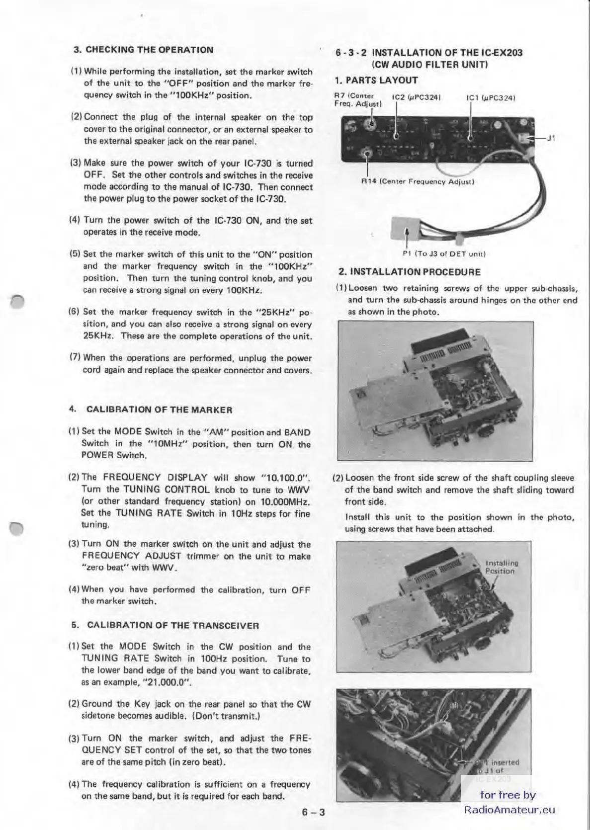
6 -3 - 2 INSTALLA
TIO
N OF T
HE
IC
-E
X203
(CW AUDIO FILTER UNI
T)
1. PARTS L
AY
OUT
P1
ITo
J3
0fOETuniti
2. I
NS
TALLATION PROCEDURE
(1)
Loosen
two
retaining screws
of
the upper sub-chassis,
and turn the sub-chassis around hinges on
th
e other end
as
shown
in
the photo.
(2)
Loosen the front side screw of the shaft coupling sleeve
of
the band switch and remove the shaft sliding toward
front side.
Install this unit
to
the position shown
in
the photo,
using
SQ'SWS
that have been attached.
for
free
by
RadioAmateur.eu

 Loading...


