(31
Rep
lace the shaft and the upper sub-chassi
s.
Unplug
Pll
i
ns
erted to J3 of the
OET
unit and plug it
to
J1
of
IC
·EX203.
(4)
Plug
Pl of
IC
-EX203
to
J3 of the
OET
unit. Tighten the
retaining
screWl
of the sub-chassls.
(5lThis unit does not require an adjustment, and provides
150Hz/6dB pass band when the set
is
in
the
CW
mode.
6 - 3 - 3 INSTALLATION OF
THE
IC-EX202 (LOA UNIT)
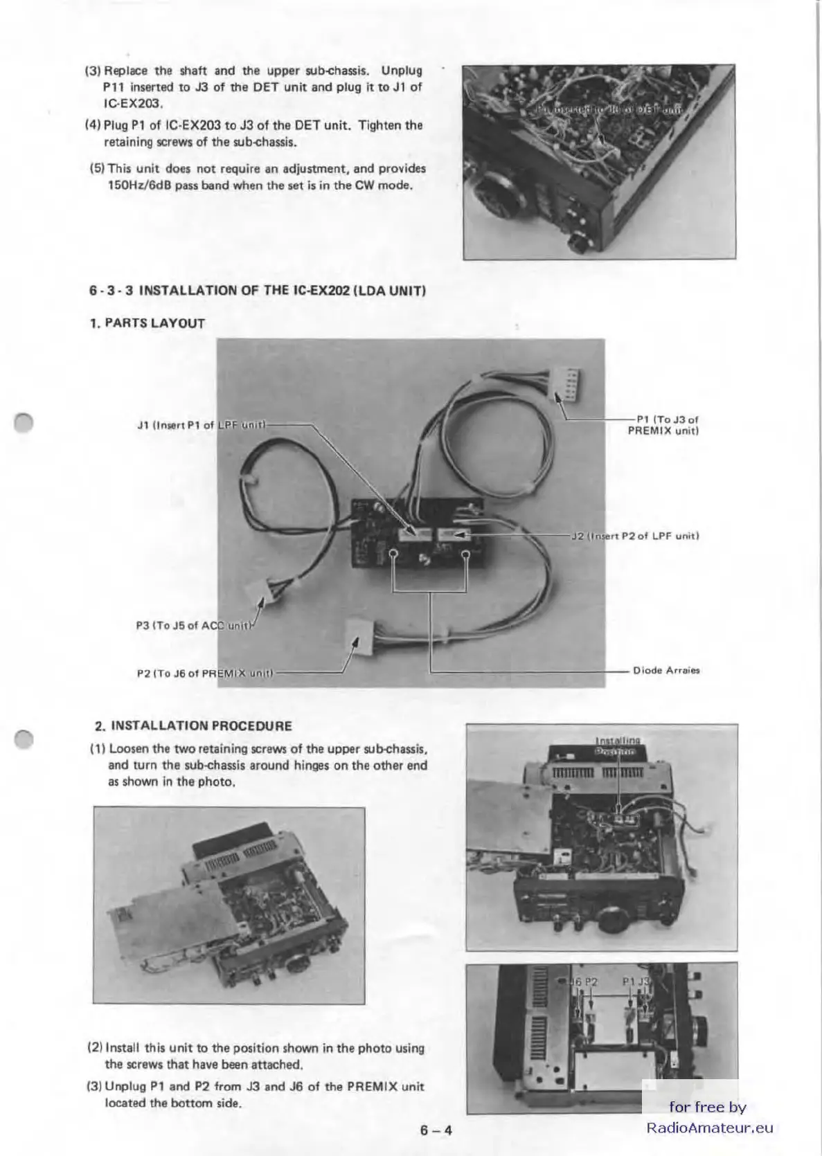
1. PARTS
LAYOUT
P3 ITo
J5
of
L-
-'i---
"11To
J3
of
PREMIX
unit!
J2
','o
i,n
p2
of
LPF
unit)
P2lTO
J6
of
PR
ii
MIX
".:!:!.:====
__
~~_.::===::
=::
====r-
-O
'
odll
Au.
ln
2. INSTALLATION PROCEDURE
(1) Loosen the
two
retaining screws of the upper sub-chassis,
and turn the sub-chassis around hinges on the other end
as
shown
in
the photo,
(2)
Install th
is
unit to the position shown
in
the photo using
the screws that
have been attached.
(3) Unplug
Pl
.nd
P2 from J3 and
J6
of
the PREMIX unit
located the bottom side.
6-4
for
free
by
RadioAmateur.eu

 Loading...


