6 - 3 -6 INSTALLATION OF THE FL-30
1. INSTALLATION PROCEDURE
(1) Loosen two retaining screws of the upper sub-chassis,
and turn the sub-chassis over around hinges on the other
end
as
shown
in
the photo.
Lnll
alhn
8
oolitLon
(2) Unscrew the screws retaining the 2nd I F unit board,
then
turn it over so that
foil
side of the board can
be
seen.
-
(3)
The location for the filter
is
shown
in
the photo. The
holes for mounting the
legs
and the leads of the filter
a
re
predrilled.
Be
sure
to
orient the filter
$0
that the in
put
terminal
(indicated on the bottom) of the filter
is
facing the same
direction
as
sho
wn
on the photo.
Insert the filter flush with the board, bend the leads and
legs
flush with the opposite side of the board and solder
them
In.
Trim the leads even with the solder
poinu
. This com-
pletes the Instellation.
6-8
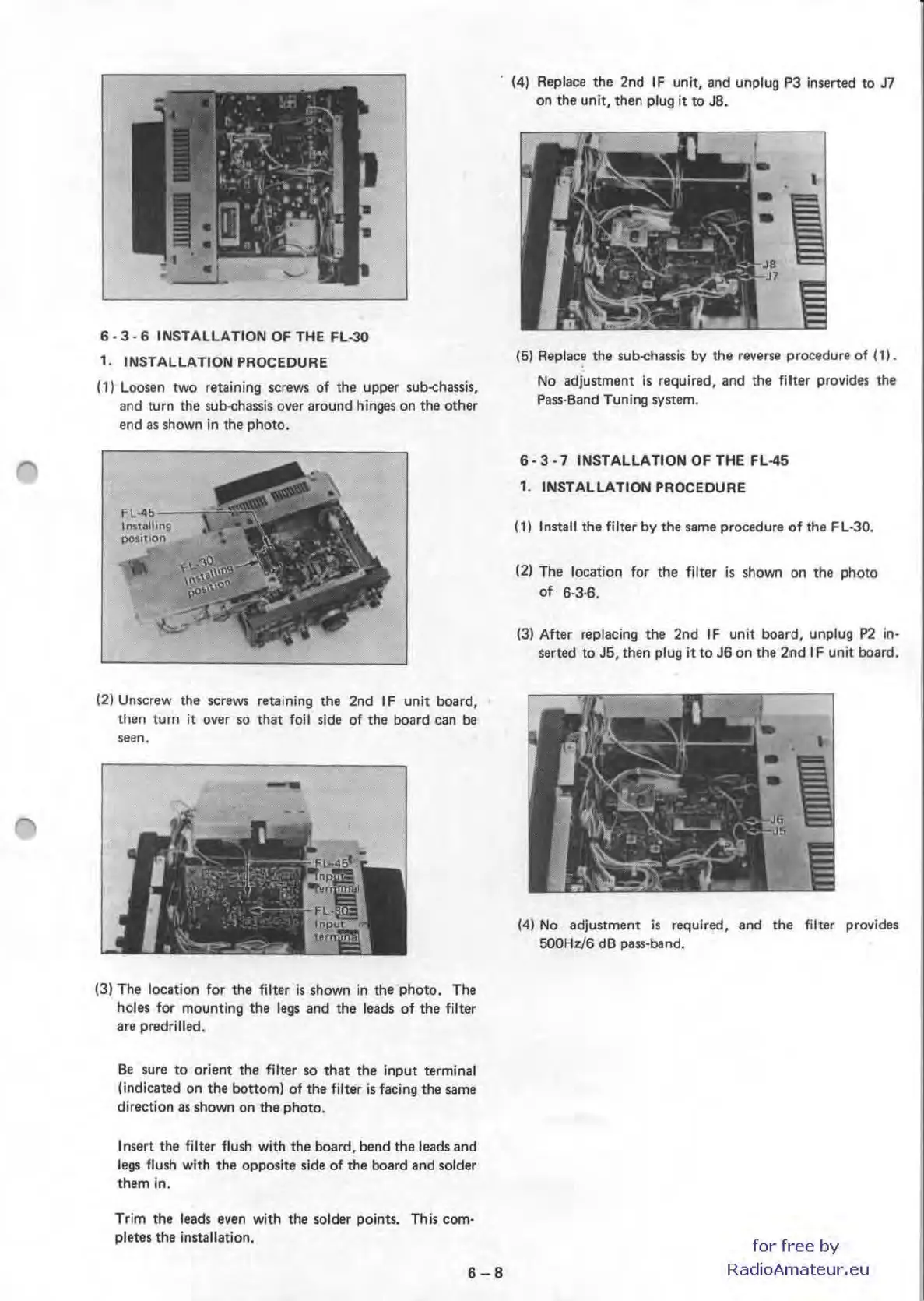
(4)
Replace the 2nd
IF
unit, and unplug P3 inserted to J7
on the unit, then
plug
it
to
J8.
(5) Replace the sub-chassis
by
the reverse procedure of
(1).
No
adjustment is required, and the filter provides the
Pa
ss-Band Tuning system.
6 - 3
-7
INSTALLATION OF THE FL-45
1. INSTALLATION PROCEDURE
(1) Install the filter by the same procedure
of
the FL-30.
(2) The location for the filter
is
shown
on
the photo
of
6-3·6.
(3) After replacing the 2nd
IF
unit board, unplug P2 in-
serted to J5, then plug
it
to J6 on the
2nd
I F unit board.
(4)
No
adjustment
is
required, and the filter provides
5OOHz/6
dB pass·band.
for
free
by
RadioAmateur.eu

 Loading...


