2. INSTALLATION PROCEDURE
(1) Remove the eight screws
at
each end
of
the rear panel.
(2)
Turn over the rear panel right side
or
put
it on the
chassis, and unplug coaxial cables from
J1
and J3 on the
LPF
unit.
(3)
Install this unit to the position shown
in
the photo using
the screws
that
have been attached.
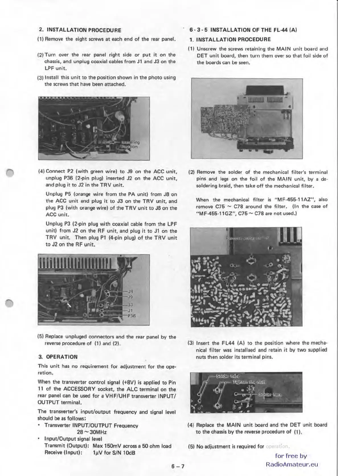
(4) Connect
P2
(with green wire)
to
J9
on the
ACC
unit,
unplug P36 (2-pin plug) inserted J2 on the
ACC
unit,
and plug
it
to
J2
In
the TRV unit.
Unplug
P5
(orange wire from the
PA
unit) from
J8
on
the
ACC
unit and plug
it
to
J3
on the TRV unit, and
plug
P3
(with orange wire) of the TRV unit to
J8
on the
ACC
unit.
Unplug
P3
(2-pin plug with coaxial cable from the LPF
unit) from
J2
on
the RF unit, and plug it
to
J1
on the
TRV unit. Then plug Pl (4-pin plug) of the TRV unit
to
J2
on the
RF
unit.
(5)
Replace unpluged connectors and the reaf panel
by
the
reverse procedure
of
(1) and (2).
3.
OPERATION
This unit has no requirement for adjustment for the ope·
ration.
When
the transverter control signal (+8V)
is
applied to P
in
11
of the ACCESSORY socket, the ALC terminal
on
the
rear panel can be used for a VHF/UHF tranwerter INPUT/
OUTPUT terminal.
The transverter's
input/output
frequency and signal
should be
as
follows:
Transverter INPUT/OUTPUT Frequency
28-30MHz
Input/O
utput
signal level
level
Transmit (Output):
Max
150mV across a
50
ohm load
Receive (Input):
l~V
for SIN
lOde
6-7
6·3·5
INSTALLATION
OF
THE
Fl-44
(A)
1. INSTALLATION PROCEDURE
(1) Unscrew the screws retaining the
MA
IN
unit board and
OET unit board, then turn them over
so
that
foil
side
of
the boards can be seen.
(2) Remove the solder of the mechanical filter's terminal
pins and
legs
on
the foil of the
MAIN
unit, by a de·
soldering braid, then take off the mechanical filter.
When
the mechanical filter
is
"MF455·11AZ",
also
remove C75 - C78 around the filter. (In the case
of
"M
F-455·11GZ",
C75""
C78 are
not
used.)
(3)
Insert the FL44
(A)
to the position where the mecha·
nical filter was installaed and retain
it
by
two supplied
nuts then solder its terminal pins.
(4) Replace the
MAIN
unit board and the DET unit board
to
the chassis
by
the reverse procedure
of
(1).
(5)
No
adjustment
is
required for operation.
for
free
by
RadioAmateur.eu

 Loading...


