(12) Turn over the rear panel right side, and unplug coaxial
cables from
J1
and J3 on the
LPF
board.
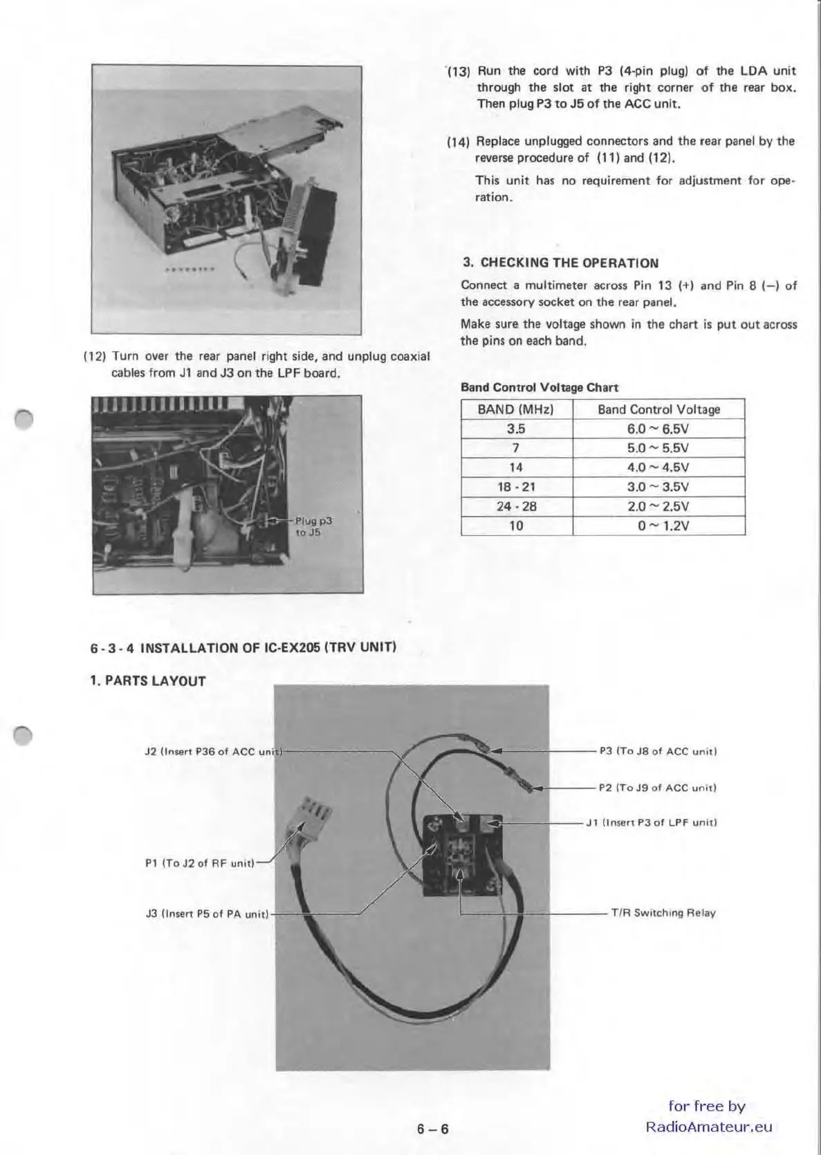
6 · 3 · 4 INSTALLATION OF
IC
·EX205ITRV
UNIT)
1. PARTS
LAYOUT
J2
Unsert
PJ6
01 ACC
,,'11-------,/
Pl
(To
J2
01
AF
,";,,--1
J3
(ln
se"
P5 01 PA
";;"'
-1-
- 1
-(13) Run the cord with
P3
14·pin plug)
of
the
LOA
unit
through the slot at the right corner of
the rear box.
Then plug
P3
to
J5
of
the
ACe
unit.
(14) Replace unplugged connectors and the rear panel by the
reverse procedure of
Ill)
and (12).
This unit has no requirement for
adjustment for ope·
ration.
3.
CHECKING THE OPERATION
Connect a multimeter across
Pin
13
(+) and
Pin
B
(-I
of
the accessory socket on the rear
panel.
Make
sure the voltage shown
in
the chart
is
put
out
across
the pins on each band.
Band
Control Voltage Chart
BA
ND
(MHz)
Band Control Voltage
3
.5
6.0-6.5V
7
5.0 - 5.5V
I.
4.0 - 4.5V
18 - 21
3.0
.....
3.5V
2'·28
2.0 -
2.5V
10
0
.....
1.2V
'_
--
-+
--
-
'PJIToJ8
01
ACC
un'tl
~"
'f----
P2 ITo
J9
01
ACC
unIt!
--
-t--
"
t1n
!t!
~t
PJ
of LPF
un
ll)
L--t
-J'-
+---TI
A Switch
ing
A'lev
6-6
for
free
by
RadioAmateur.eu

 Loading...


