D Command table (Continued)
*4 When sending the power ON command (18 01), you need
to repeatedly send “FE” before the standard format. The
following is the approximate number of needed repetitions.
• 115200 bps: 150 “FE”s
• 57600 bps: 75 “FE”s
• 38400 bps: 50 “FE”s
• 19200 bps: 25 “FE”s
• 9600 bps: 13 “FE”s
• 4800 bps: 7 “FE”s
×7
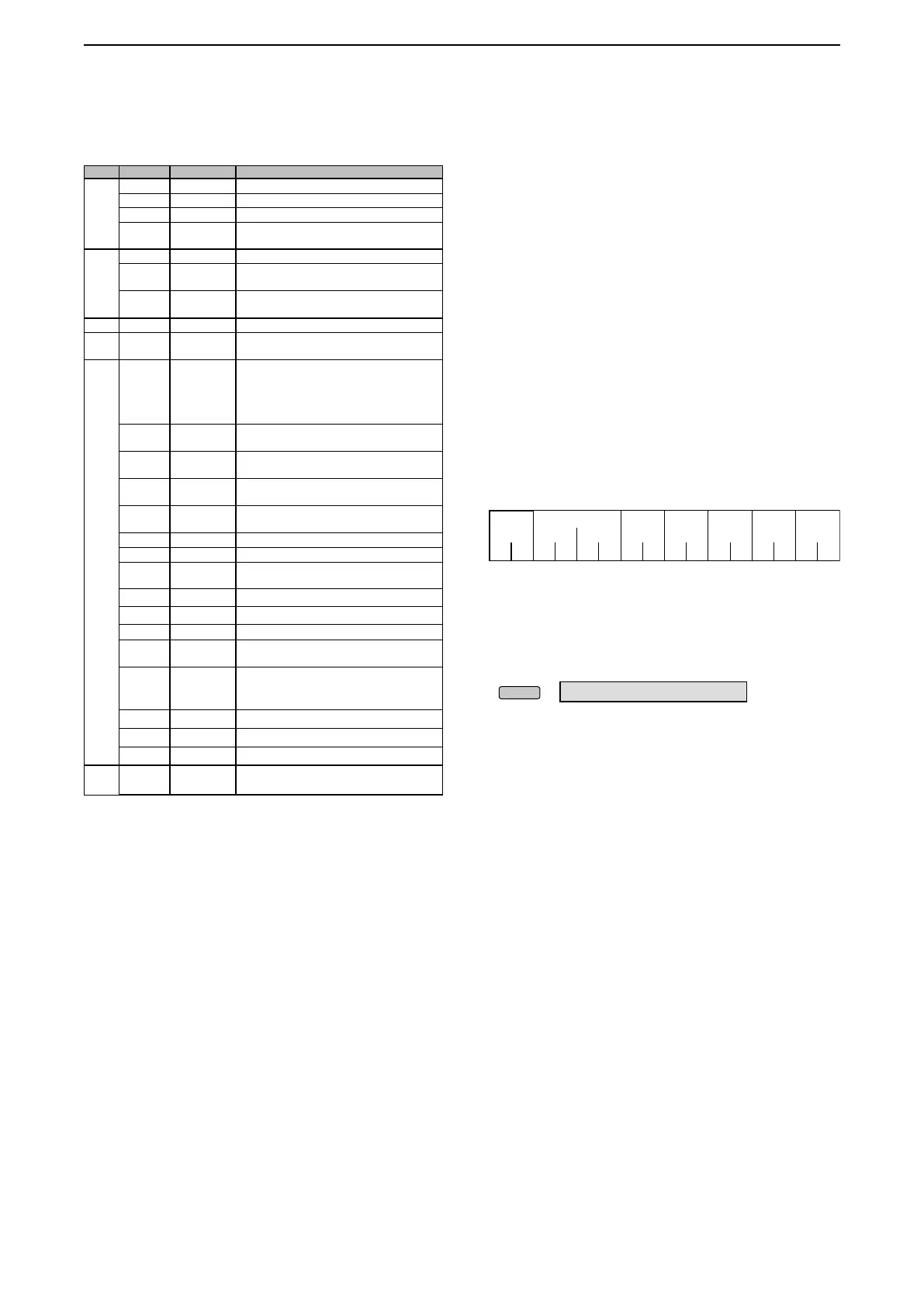
Example: When using 4800 bps
F 89EFEF E E 10810 DF
Preamble 7610’s
address
Controller’s
address
Command
Sub
command
Post
amble
*5 Read only data
*6 To insert a counter, rst clear the other channel’s counter.
*7
When you use the [USB 1] port, you need to select “Unlink
from [REMOTE]” in the “CI-V USB port” item, and you
need to select “115200” in the “CI-V Baud Rate” item.
» SET > Connectors > CI-V
You can use the [LAN] port, regardless of those settings.
You cannot use the [REMOTE] terminal, regardless of
those settings.
*1 If the Antenna Type is set to
“
RX-I/O,” command “01 (RX
ANT ON)” is invalid and “00 (RX ANT OFF)” is always
returned.
*2 If the Antenna Type is set to “RX-ANT,” command “01
(ON)” is invalid and “00 (OFF)” is always returned.
*3 In the CW mode, if the [TRANSMIT] or an external TX
switch is ON, or the Break-in function is ON, a message
will be transmitted as CW code when you send it from
your PC.
*(Asterisk) Send/read data
Cmd. Sub cmd. Data Description
1E 00 Read number of available TX frequency band
01 see p. 10 Read TX band edge frequencies
02 Read number of user-set TX frequency band
03* see p. 10 Send/read user-set TX band edge
frequencies
21* 00 see p. 13 RIT frequency
01 00 or 01 RIT setting
(00=OFF, 01=ON)
02 00 or 01
∂
TX setting
(00=OFF, 01=ON)
25* see p. 13 Main or sub band frequency
26* see p. 13 Send/read the operating mode and lter
setting (for both Main and Sub bands)
27* 00 see p. 14 Read the Scope waveform data
( Only when “Scope ON/OFF status”
(Command: 27 10) and “Scope data output”
(Command: 27 20) are set to “ON,” outputs
the waveform data to the controller.)
10 00 or 01 Scope ON/OFF status
(00=OFF, 01=ON)
11*
7
00 or 01 Scope wave data output
(00=OFF, 01=ON)
12 00 or 01 Main or Sub scope setting
(00=Main, 01=Sub)
13 00 or 01 Single/Dual scope setting
(00=Single, 01=Dual)
14 see p. 14 Scope Center mode or Fixed mode setting
15 see p. 14 Span setting in the Center mode Scope
16 see p. 14 Edge number setting in the Fixed mode
Scope
17 see p. 14 Scope hold function ON or OFF
19 see p. 15 Scope Reference level setting
1A see p. 15 Sweep speed setting
1B 00 or 01 SCOPE > Scope during Tx (CENTER TYPE)
(00=OFF, 01=ON)
1C 00 ~ 02 SCOPE > CENTER Type Display
(00=Filter center, 01=Carrier point center,
02=Carrier point center (Abs. Freq.))
1D see p. 15 Scope VBW setting
1E see p. 15 Scope Fixed edge frequencies
1F see p. 15 Scope RBW setting
28 00 00 ~ 08 Voice TX Memory
(00=Stop, 01=T1 to 08=T8)
Remote control
9

 Loading...


