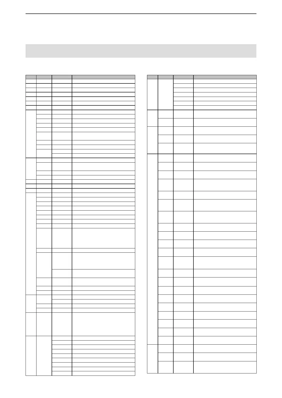
Cmd. Sub cmd. Data Description
00 see p. 10 Send frequency data (transceive)
01 see p. 10 Send mode data (transceive)
02 see p. 10 Read band edge frequencies
03 see p. 10 Read operating frequency
04 see p. 10 Read operating mode
05 see p. 10 Set operating frequency
06 see p. 10 Set operating mode
07 Select the VFO mode
B0 Exchange main and sub bands
B1 Equalize main and sub bands
C0 Turn OFF Dualwatch
C1 Turn ON Dualwatch
C2* 00 or 01 Send/read the dualwatch setting
(00=OFF, 01=ON)
D0 Select the main band
D1 Select the sub band
D2* 00 Send/read main band selection
01 Send/read sub band selection
08 Select the Memory mode
0001 to 0099 Select the Memory channel
(0001=M-CH01, 0099=M-CH99)
0100 Select program scan edge channel P1
0101 Select program scan edge channel P2
09 Memory write
0A Memory copy to VFO
0B Memory clear
0E 00 Cancel the scan
01 Start a Programmed/memory scan
02 Start a Programmed scan
03 Start a
∂
F scan
12 Start a Fine programmed scan
13 Start a Fine
∂
F scan
22 Start a Memory scan
23 Start a Select memory scan
Ax
(x=1 to 7)
Select
∂
F scan span
( x=1 (±5 kHz), x=2 (±10 kHz),
x=3 (±20 kHz), x=4 (±50 kHz),
x=5 (±100 kHz), x=6 (±500 kHz),
x=7 (±1 MHz))
B0 Clear the Select channel setting
B1 Set as select channel
( The previously set number by CI-V is set
after turning power ON, or “1” is selected if
no selection is performed.)
01 to 03 Set the channel as a Select channel
(01=SEL1, 02=SEL2, 03=SEL3)
B2 00 to 03 Set the Select memory scan channel
(00=ALL, 01=SEL1, 02=SEL2, 03=SEL3)
D0 Set Scan resume OFF
D3 Set Scan resume ON
0F 00 Read Split OFF setting
01 Read Split ON setting
00 Turn OFF the Split function
01 Turn ON the Split function
10* 00 to 08 Send/read the tuning step
(
00=OFF (10 Hz or 1 Hz),
01=100 Hz, 02=1 kHz, 03=5 kHz,
04=9 kHz, 05=10 kHz,
06=12.5 kHz, 07=20 kHz,
08=25 kHz)
11* 00 Send/read attenuator OFF setting
03 Send/read 3 dB attenuator setting
06 Send/read 6 dB attenuator setting
09 Send/read 9 dB attenuator setting
12 Send/read 12 dB attenuator setting
15 Send/read 15 dB attenuator setting
18 Send/read 18 dB attenuator setting
21 Send/read 21 dB attenuator setting
24 Send/read 24 dB attenuator setting
Cmd. Sub cmd. Data Description
27 Send/read 27 dB attenuator setting
30 Send/read 30 dB attenuator setting
33 Send/read 33 dB attenuator setting
36 Send/read 36 dB attenuator setting
39 Send/read 39 dB attenuator setting
42 Send/read 42 dB attenuator setting
45 Send/read 45 dB attenuator setting
12* 00*
1
00 or 01 Select/read ANT1 selection
(00=RX ANT OFF, 01=RX ANT ON)
01*
1
00 or 01 Select/read ANT2 selection
(00=RX ANT OFF, 01=RX ANT ON)
13 00 Speech all data with voice synthesizer
(S meter level, frequency and mode)
01 Speech the operating frequency and S meter
level by voice synthesizer
02
Speech the operating mode by voice synthesizer
L The mode is announced after the ongoing
speech.
14* 01 0000 ~ 0255 Send/read the AF level
(0000=min. to 0255=max.)
02 0000 ~ 0255 Send/read the RF gain level
(0000=min. to 0255=max.)
03 0000 ~ 0255 Send/read the squelch level
(0000=min. to 0255=max.)
05 0000 ~ 0255 Send/read the APF level (10 Hz steps)
( 0000=Pitch–550 Hz, 0128=Pitch,
0255=Pitch+550 Hz)
06 0000 ~ 0255 Send/read the NR level
(0000=0%, 0255=100%)
07 0000 ~ 0255 Send/read inner [TWIN PBT] position
( 0000=max. CCW, 0128=center, 0255=max.
CW)
08 0000 ~ 0255 Send/read outer [TWIN PBT] position
( 0000=max. Counter Clockwise, 0128=center,
0255=max. Clockwise)
09 0000 ~ 0255 Send/read CW pitch (5 Hz steps)
( 0000=300 Hz, 0128=600 Hz, 0255=900 Hz)
0A 0000 ~ 0255 Send/read RF power
( 0000=min. to 0255=max.)
0B 0000 ~ 0255 Send/read MIC gain
( 0000=min. to 0255=max.)
0C 0000 ~ 0255 Send/read keying speed
(0000=6 wpm to 0255=48 wpm)
0D 0000 ~ 0255 Send/read Nothc lter setting
( 0000=max. Counter Clockwise, 0128=center,
0255=max. Clockwise)
0E 0000 ~ 0255 Send/read the COMP level
(0000=0 to 0255=10)
0F 0000 ~ 0255 Send/read the Break-IN Delay setting
(0000=2.0 d to 0255=13.0 d)
12 0000 ~ 0255 Send/read NB level
(0000=0% to 0255=100%)
13 0000 ~ 0255 Send/read the DIGI-SEL shift amount
( 0000=min. to 0255=max.)
14 0000 ~ 0255 Send/read DRIVE gain
(0000=0% to 0255=100%)
15 0000 ~ 0255 Send/read Monitor audio [MONI] level
(0000=0% to 0255=100%)
16 0000 ~ 0255 Send/read the VOX gain
(0000=0% to 0255=100%)
17 0000 ~ 0255 Send/read the Anti VOX gain
(0000=0% to 0255=100%)
19 0000 ~ 0255 Send/read LCD backlight brightness
(0000=0% to 0255=100%)
15 01 00 or 01 Read noise or S-meter squelch status
(00=Close, 01=Open)
02 0000 to 0255 Read S-meter level
(0000=S0, 0120=S9, 0241=S9+60 dB)
05 00 or 01 Read various squelch (tone squelch, and so
on) status
(00=Close, 01=Open)
D Command table
NOTE: Operation to the some control dials overrides CI-V commands. If a control dial (such as the AF Volume dial that
has a mark on it) is rotated after sending a CI-V command, the command will be overwritten by the operation.
11*
Remote control
3

 Loading...


