The S-meter signal is applied to the main
CPU (MAIN unit
IC1
2
pin
93)
and is compared
with the threshold level
set by
the [SQL]
control. The
[SQL] setting Is picked up
at the A/D
converter (SW-A unit IC7) and then applied
to the sub CPU
(ICS). The CPU compares the S-meter signal
and [SQL]
setting to close or open the squelch.
In addition, the noise squelch signal
(FMND) from the FM IF
1C
is applied to the main
CPU (pin
92)
in FM mode. A
portion of the AF signals from the FM
IF
1C
(IF unit IC15, pin
9)
are
applied to the active filter
section
(pin
8)
where noise
components above
20
kHz are
amplified. The signals are
rectified at the noise detector
section and then output from
pin 1 3. The resulting signal is applied
to the main CPU via
the “FMND/ASQN" signal line.
4-1-16
SSB/CW DEMODULATOR
CIRCUIT
(IF UNIT)
While in SSB or CW mode (DSP
detection is QFF), the 4th
IF
signals from
Q14
are
mixed with the BFO signal
from the
PLL
unit
at the
product detector
(IC14 pin
6).
The
detected
AF signal from IC14 (pin
2)
is
applied to the AF selector
switch (IC1
6,
IC17).
4-1-17
AM DEMODULATOR CIRCUITS
(IF UNIT)
While in AM mode (DSP detection
is OFF), the 4th
IF
signals from the
IF
amplifier
(Q14)
are amplified
at Q15 and
detected at D8. The detected AF signal
is then applied
to
the AF
selector switch
(IC16, IC17) via
Q16.
4-1-18
FM DEMODULATOR
CIRCUIT (IF UNIT)
While in FM mode, the
3rd
IF signals from
the buffer
amplifier
(Q12)
are applied to the FM
IF
1C
(IC15 pin
5)
where the IF signals are
converted
into
AF
signals.
X2 is
used for
quadrature detector.
The detected AF signals
are
then
applied
to
the AF selector
switch (IC16, IC17) via
Q30
and Q31.
4-1-19
AF
SELECTOR SWITCH (IF
UNIT)
The AF signal from one of the
detector circuits is applied
to
the AF selector switch (IC16, IC17).
IC16 and IC17 consist
of
8
analog
switches which are selected
with a mode signal
and
the squelch
control signal.
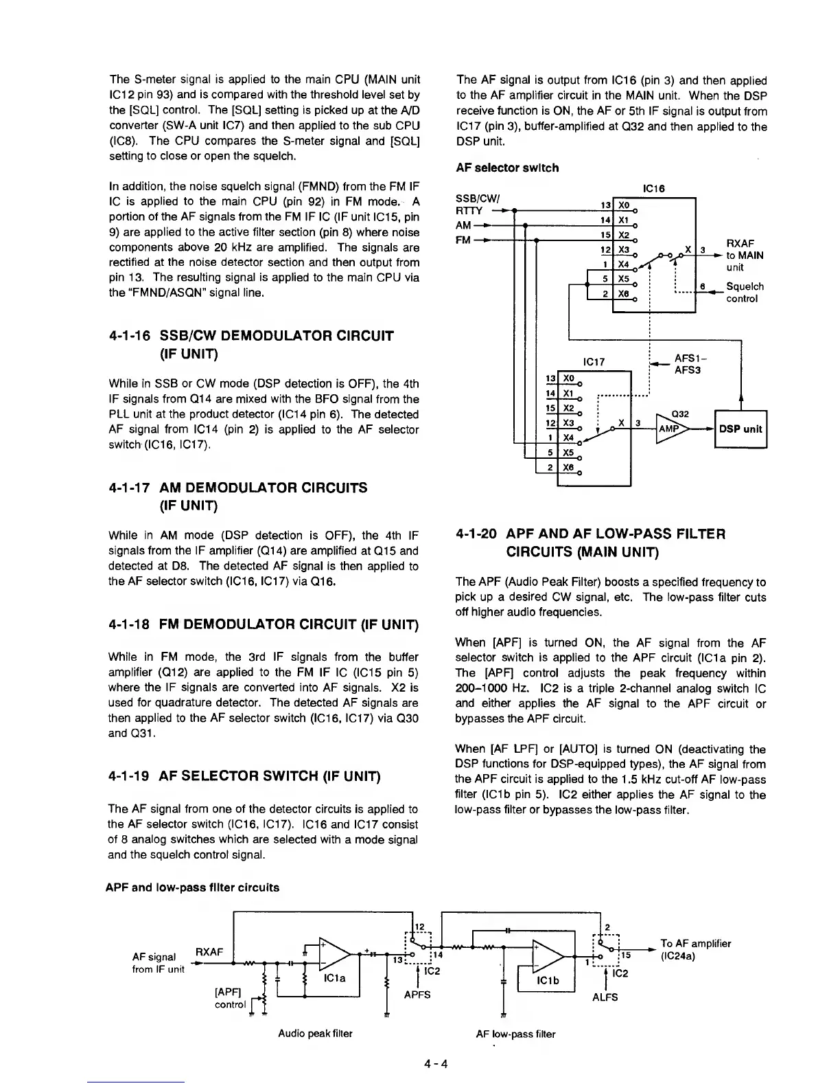
The AF signal is
output from IC1
6
(pin
3)
and then
applied
to the
AF amplifier circuit in the
MAIN unit. When
the
DSP
receive
function is ON,
the
AF
or 5th IF signal
is output from
IC17 (pin
3),
buffer-amplified
at
Q32 and then applied
to the
DSP unit.
AF selector switch
IC16
4-1-20
APF AND AF
LOW-PASS FILTER
CIRCUITS
(MAIN UNIT)
The APF (Audio Peak Filter)
boosts a specified frequency
to
pick
up a
desired
CW signal, etc. The low-pass
filter
cuts
off higher audio
frequencies.
When
[APF] is turned ON, the
AF signal from the
AF
selector
switch is applied to the
APF circuit (IC1a
pin
2).
The [APF] control
adjusts the peak frequency
within
200-1000
Hz. IC2
is a triple 2-channel analog
switch
1C
and either applies the AF signal
to the
APF circuit
or
bypasses the
APF circuit.
When
[AF LPF] or [AUTO] Is turned
ON (deactivating
the
DSP functions
for DSP-equipped
types), the AF signal
from
the
APF circuit is applied to
the 1
.5
kHz cut-off AF
low-pass
filter
(ICIb pin
5).
IC2 either applies the AF
signal to the
low-pass filter
or bypasses the
low-pass filter.
APF and low-pass filter circuits
AF signal
from IF unit
To AF amplifier
(IC24a)
Audio peak filter
AF low-pass filter

 Loading...


