5-4
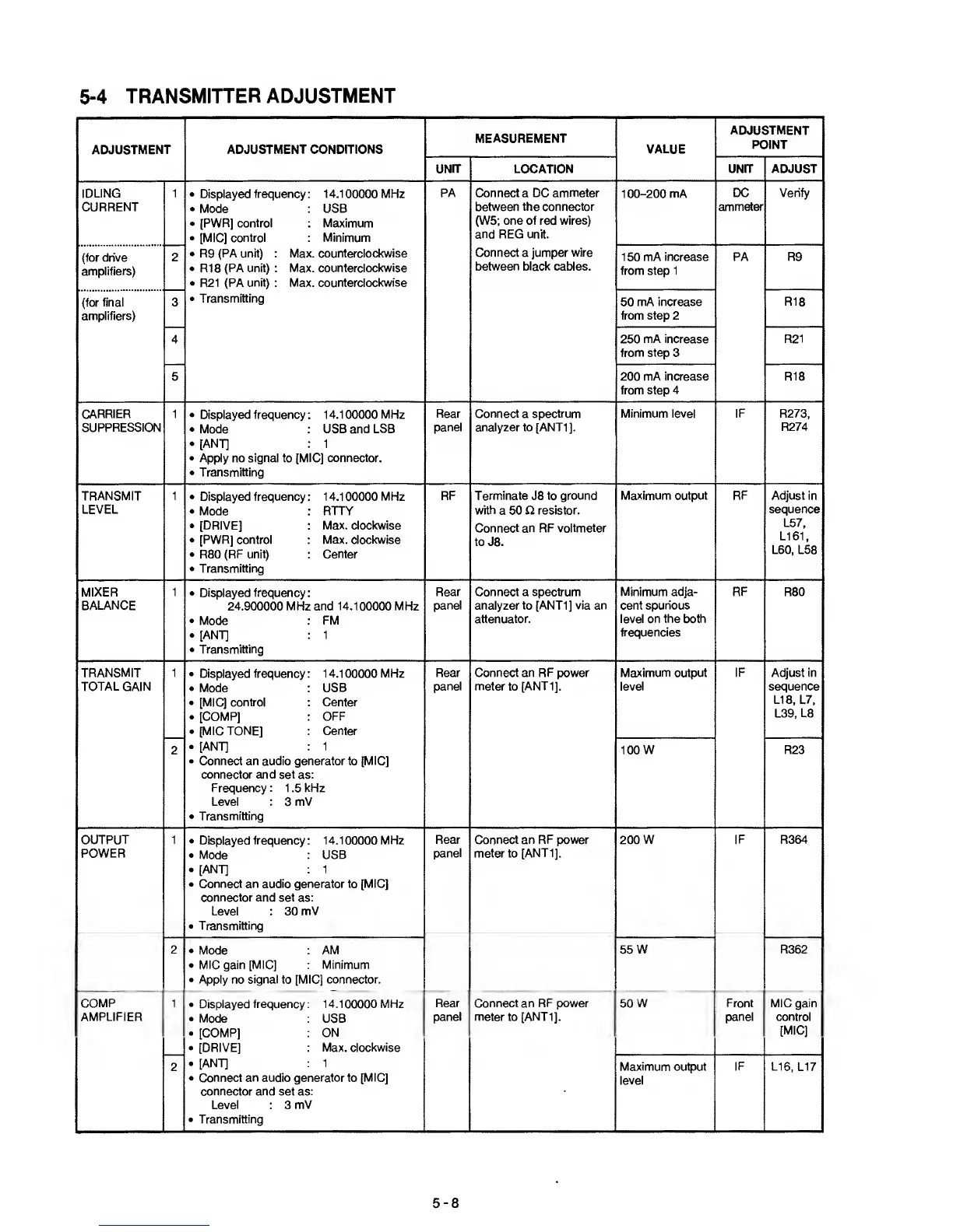
TRANSMITTER ADJUSTMENT
ADJUSTMENT
ADJUSTMENT CONDITIONS
MEASUREMENT
VALUE
ADJUSTMENT
POINT
UNIT LOCATION UNIT ADJUST
IDLING
CURRENT
1 •
Displayed frequency : 1 4.1
00000
MHz
.
Mode
: USB
•
[PWR] control : Maximum
•
[MIC]
control : Minimum
•
R9
(PA unit) : Max. counterclockwise
•
R18
(PA unit) : Max. counterclockwise
•
R21
(PA
unit)
: Max.
counterclockwise
•
Transmitting
PA
Connect a DC
ammeter
between
the connector
(W5; one of red wires)
and REG unit.
Connect
a jumper
wire
between
black cables.
1
00-200
mA
DC
ammeter
Verify
(for drive
amplifiers)
2
150 mA
increase
from step 1
PA
R9
(for
final
amplifiers)
3 50
mA increase
from step 2
R18
4 250
mA increase
from step
3
R21
5
200 mA increase
from step 4
R18
CARRIER
SUPPRESSION
1 •
Displayed frequency: 14.100000 MHz
•
Mode
: USB and LSB
•
[ANT]
; 1
•
Apply no
signal
to [MIC]
connector.
•
Transmitting
Rear
panel
Connect
a
spectrum
analyzer to [ANTI].
Minimum level IF R273,
R274
TRANSMIT
LEVEL
•
Displayed
frequency
: 1 4.1 00000
MHz
.
Mode
: RTTY
•
[DRIVE] : Max. clockwise
•
[PWR] control : Max. clockwise
•
R80
(RF unit) : Center
•
Transmitting
RF Terminate
J8
to ground
with
a 50
O resistor.
Connect
an RF
voltmeter
to J8.
Maximum output RF Adjust in
sequence
L57,
L161,
L60,
L58
MIXER
BALANCE
1
•
Displayed frequency
:
24.900000 MHz and
14.100000
MHz
•
Mode
FM
•
[ANT] : 1
•
Transmitting
Rear
panel
Connect a spectrum
analyzer to [ANTI] via an
attenuator.
Minimum adja-
cent
spurious
level on the both
frequencies
RF
R80
TRANSMIT
TOTAL GAIN
1 •
Displayed frequency : 14.100000 MHz
.
Mode :
USB
•
[MIC] control Center
.
[COMP] :
OFF
•
[MIC TONE] : Center
.
[ANT]
: 1
•
Connect an audio
generator
to
[MIC]
connector and set
as:
Frequency : 1
.5
kHz
Level : 3 mV
•
Transmitting
Rear
panel
Connect an RF power
meter to
[ANTI].
Maximum output
level
IF
Adjust in
sequence
LI
8,
L7.
L39, L8
2
100 W R23
OUTPUT
POWER
1
•
Displayed
frequency
:
14.1
00000
MHz
•
Mode :
USB
•
[ANT] : 1
•
Connect an audio generator to [MIC]
connector and set
as:
Level : 30
mV
•
Transmitting
Rear
panel
Connect
an RF power
meter to
[ANTI].
200
W IF R364
2
•
Mode
AM
•
MIC gain [MIC] : Minimum
•
Apply no
signal
to
[MIC] connector.
55
W R362
COMP
AMPLIFIER
1
•
Displayed frequency : 14.100000 MHz
.
Mode : USB
.
[COMP] : ON
•
[DRIVE] :
Max. clockwise
.
[ANT]
: 1
•
Connect
an
audio generator to
[MIC]
connector and set as:
Level
: 3
mV
•
Transmitting
Rear
panel
Connect an RF p>ower
meter to [ANTI].
SOW Front
panel
MIC gain
control
[MIC]
2
Maximum output
level
Lie.
L17
5-8