4-1-21
AF
AMPLIFIER
CIRCUIT (MAIN UNIT)
The AF
amplifier
amplifies
the
AF
input signal to a
suitable
driving
level for the
speaker.
The
AF signal
from
the AF
low-pass filter (IC1 b) is
applied
to
the
AF
amplifiers (IC24a,
IC7a).
The
CW
side tone/
transmit monitor
signal and
beep tone
are amplified at tC7b
and IC24b,
respectively.
The
amplified
signals from IC7a,
IC7b and lC24b are
applied to the
[TONE]
control
(VR-A unit
R32)
and then to
the
VGA
(Voltage
Controlled
Amplifier, IC16)
circuit. The
AF
gain
setting
from the
main
CPU
(pins
42-51)
is con-
verted
to
DC
voltage at R58-R77
and applied
to the VGA
control
terminal
(IC1
6
pin
8)
via IC20a.
The
AF
signal
from
1C16
(pin
9)
is
power-amplified
at
IC6
to
drive
the
speaker.
4-2-2
VOX
CIRCUIT
(MAIN
UNIT)
The
VOX
(Voice-Operated-Transmission)
circuit sets trans-
mitting conditions
according to voice input.
The microphone
signal from ICS
pin
4
passes
through the
[VOX-GAIN]
control (VR-A unit R45)
and is
amplified
at
IC23b. The
signal
is then
applied to
the
VOX
comparator
(IC23d
pin
13)
to
switch
Q23,
IC17, IC22, Q5.
When voice
levels exceed the
comparator
level,
the VOX
circuit sets the
transceiver to
transmit.
On the
other hand, a
speaker
drive
signal from the AF
power amplifier (IC6)
is applied
to the antl-VOX
comparator
(IC23a
pin
3)
via the [ANTI-VOX]
control (VR-A
unit R44).
When audio output
level increases, this
comparator cuts out
the VOX
comparator
input
using 06.
4-2
TRANSMITTER
CIRCUITS
4-2-1
MICROPHONE
AMPLIFIER CIRCUIT
(MAIN AND IF UNITS)
The
microphone
amplifier
circuit amplifies
microphone
input
signals and
outputs the
amplified signals to the
balanced
modulator, DSP (PSN)
modulation circuit or
FM/AM modu-
lation circuit.
Audio
signals from
the [MIC]
connector
are amplified
at
VCA
1C
(IC8). The
amplified
signals from
pin
4 are
applied
to
the
[MIC TONE]
control
(VR-A unit R43) and
then to
the
VCA
section of IC8
(pin
7).
The
microphone gain setting
from the
main CPU
(pins 32-41)
is converted to DC
voltage
at
R38-R57
and
applied to
the
VCA
control terminal
(ICS
pin
8)
via IC20b.
The
resulting signals
from
pin
9
are then
applied
to IClOa
(IF unit) via
the “MIG2”
signal
line.
Exter-
nal
modulation
input from the [ACC(1
)]
socket
(pin
4)
is also
applied
to IClOa
(IF unit).
The
amplified signals from
IClOa are
then applied to the AF
selector switch (IC9)
for SSB
modulation
or
the
amplifier
(IClOb)
for
FM/AM modulation.
When
the DSP
modulation Is turned ON,
pins
3/5
and 13/14
of
the AF
selector switch (IC9)
are connected.
Therefore,
the
amplified signal is
applied to the DSP unit
and the
resulting
signal
(15
kHz
IF) is applied
to the mixer (ICS)
via
IC9.
4-2-3
BALANCED
MODULATOR (IF
UNIT)
The
balanced
modulator converts the AF
signal from the
microphone amplifier to a 455
kHz IF signal with a
BFO
(Beat Frequency
Oscillator)
signal.
Microphone
signals from the AF
selector switch (IC9
pins
1
,
3)
are applied to the balanced
modulator
(ICS
pin
6).
The
BFO
signal from
the
PLL unit
is
applied to
ICS
(pin
8)
as a
carrier
signal.
ICS is a double
balanced mixer 1C and
outputs a
double
side band (DSB)
signal with
-40
dB of
carrier suppression.
R273
and R274 adjust the
balanced level of ICS
for maxi-
mum carrier
suppression. The
resulting signal passes
through the 455 kHz
IF filter (FI4; FI6 when PSN modu-
lation) to suppress
unwanted sideband signals.
When DSP
modulation is turned ON, ICS functions as a
mixer. ICS
mixes the 1
5
kHz IF
signal
with a 440
kHz
LO to
obtain a 455
kHz IF signal.
In CW
and RTTY modes,
IC9
pins
2
and
3
are
connected
to
upset the balance
of
ICS
via R268 for leaking the BFO
signal as a carrier
signal. CW keying is controlled at 01
0
via
the
“WFM4” signal.
.
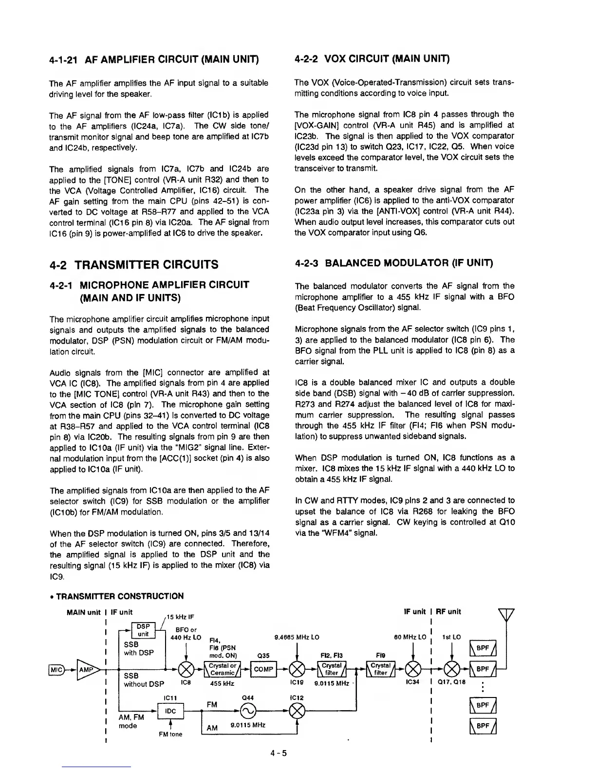
TRANSMITTER
CONSTRUCTION
4-5