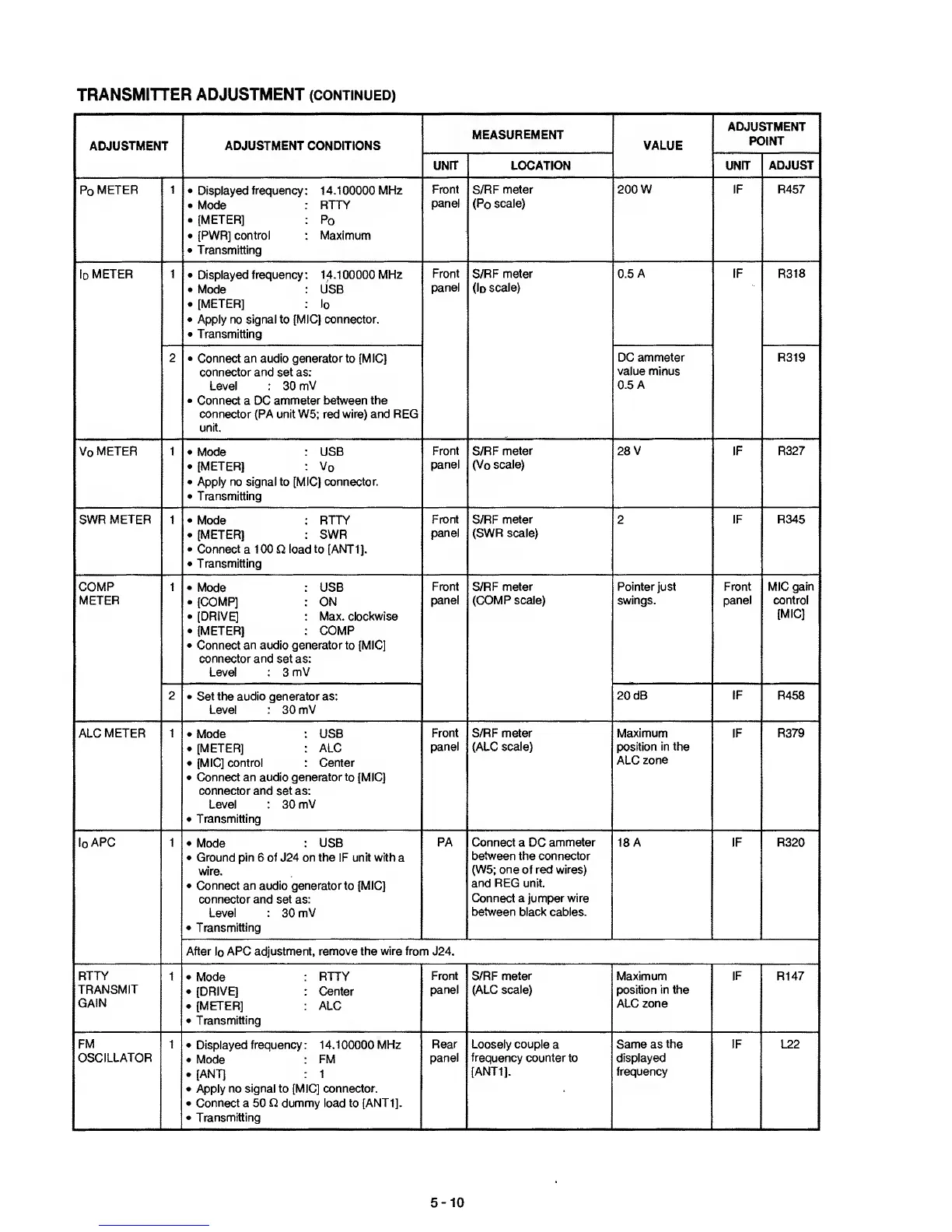
TRANSMITTER
ADJUSTMENT (CONTINUED)
ADJUSTMENT
ADJUSTMENT CONDITIONS
MEASUREMENT
VALUE
ADJUSTMENT
POINT
LOCATION UNIT
ADJUST
Po
METER
1 •
Displayed
frequency
:
14.1
00000
MHz
•
Mode
: RTTY
.
[METER] :
Po
•
[PWR] control
:
Maximum
•
Transmitting
S/RF meter
(Po
scale)
200
W
1
R457
Id
meter
1
•
Displayed frequency:
14.100000 MHz
•
Mode
:
USB
.
[METER] :
Id
•
Apply no signal to [MIC] connector.
•
Transmitting
Front
panel
S/RF meter
(Id
scale)
0.5
A
IF
R318
2 •
Connect an audio
generator
to
[MIC]
connector
and
set as:
Level :
30
mV
•
Connect a DC
ammeter between the
connector (PA unit W5; red wire) and REG
unit.
DC ammeter
value minus
0.5 A
R319
Vd
meter 1 •
Mode
: USB
.
[METER] :
Vd
•
Apply no signal to [MIC] connector.
•
Transmitting
Front
panel
S/RF
meter
(Vd
scale)
28
V IF R327
SWR
METER 1
•
Mode
: RTTY
•
[METER]
:
SWR
•
Connect a
1
00 D
load to
[ANT
1].
•
Transmitting
Front
panel
S/RF
meter
(SWR
scale)
2
R345
COMP
METER
1 .
Mode : USB
.
[COMP] : ON
•
[DRIVE] : Max. clockwise
•
[METER] : COMP
•
Connect an audio generator to [MIC]
connector and
set as:
Level :
3
mV
Front
panel
S/RF meter
(COMP scale)
Pointer
Just
swings.
Front
panel
MIC gain
control
[MIC]
2 •
Set the audio generator as:
Level :
30 mV
20 dB IF R458
ALC
METER 1 •
Mode
USB
.
[METER]
:
ALC
•
[MIC] control :
Center
•
Connect an audio
generator
to [MIC]
connector
and
set as:
Level : 30
mV
•
Transmitting
Front
panel
S/RF meter
(ALC scale)
Maximum
position
in the
ALC zone
IF R379
IdAPG
1 •
Mode
USB
•
Ground pin 6 of
J24
on the IF unit with a
wire.
•
Connect an audio generator
to
[MIC]
connector and set
as:
Level :
30
mV
•
Transmitting
PA Connect a DC ammeter
between the
connector
(W5; one of red wires)
and REG unit.
Connect a jumper wire
between black cables.
18 A IF R320
After
Id
APC adjustment, remove the
wire from
J24.
RTTY
TRANSMIT
GAIN
1 •
Mode :
RTTY
•
[DRIVE] : Center
.
[METER] :
ALC
•
Transmitting
Front
panel
S/RF
meter
(ALC scale)
Maximum
position
in
the
ALC zone
IF
R147
FM
OSCILLATOR
1 •
Displayed frequency: 14.100000 MHz
•
Mode :
FM
.
[ANT] : 1
•
Apply no
signal
to [MIC]
connector.
•
Connect a 50 £2 dummy
load
to [ANTI].
•
Transmitting
Rear
panel
Loosely couple
a
frequency counter to
[ANTI],
Same as the
displayed
frequency
IF
L22
5-10
 Loading...


