EasyManuals Logo

Icom IC-92A Service Manual

Icom IC-92A
60 pages
To Next Page IconTo Next Page
To Previous Page IconTo Previous Page
Page #8 background imageLoading...
Page #8 background image
3 - 2
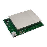
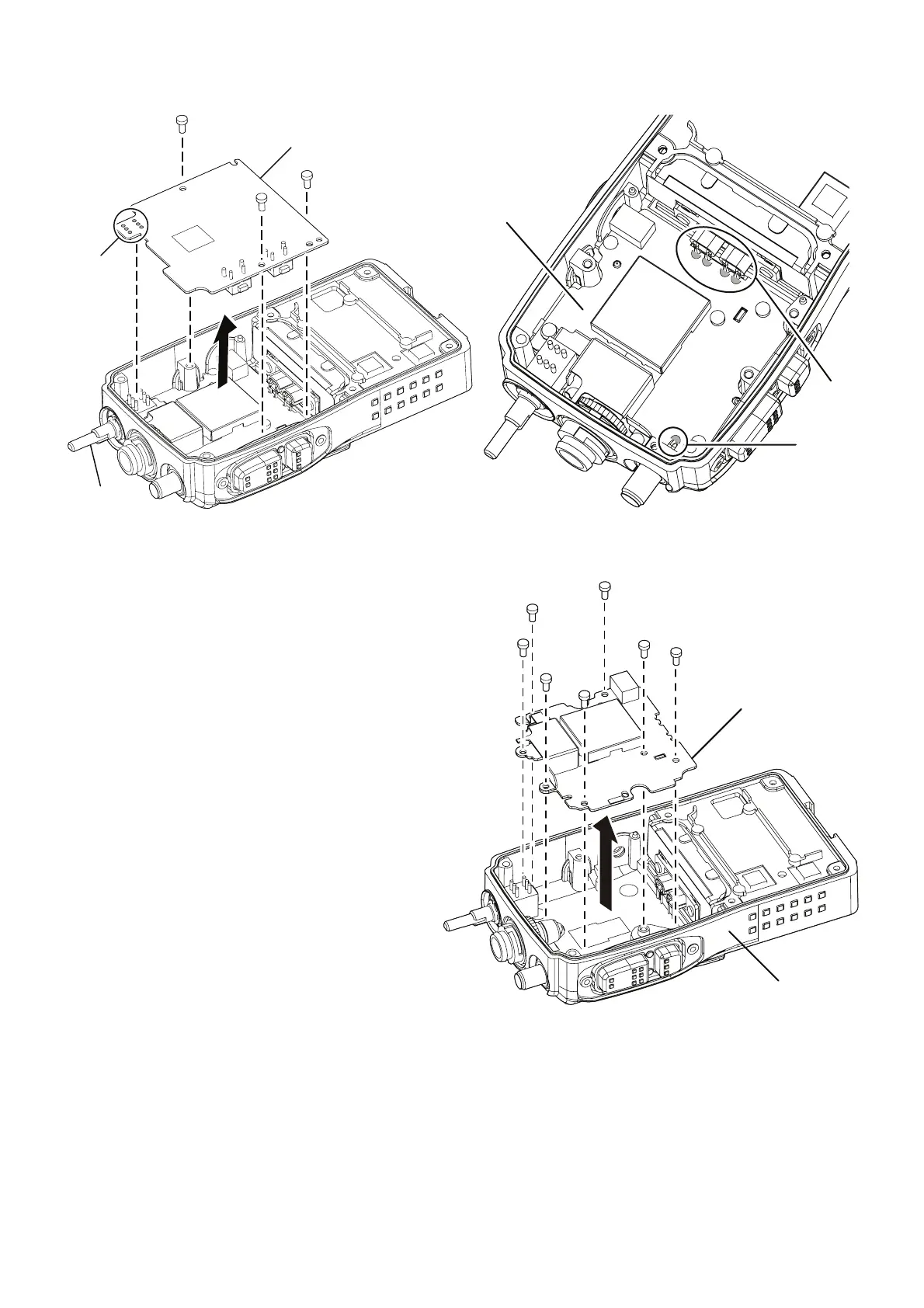
4. Removing MAIN UNIT
q Unscrew 3 screws from the MAIN UNIT.
w Unsolder 6 points at the control dial, and remove the
MAIN UNIT.
MAIN UNIT
Unsolder
6 points
Control dial
Unsolder
4 points
RF UNIT
Unsolder
1 point
5. Removing RF UNIT
q Unsolder 4 points at the contact pins.
w Unsolder 1 point at the bottom of ANT connector.
e Unscrew 7 screws from the RF UNIT, and remove the RF
UNIT from the CHASSIS.
RF UNIT
Chassis

Other manuals for Icom IC-92A

Questions and Answers:

Question and Answer IconNeed help?

Do you have a question about the Icom IC-92A and is the answer not in the manual?

Icom IC-92A Specifications

General IconGeneral
BrandIcom
ModelIC-92A
CategoryTransceiver
LanguageEnglish

Related product manuals