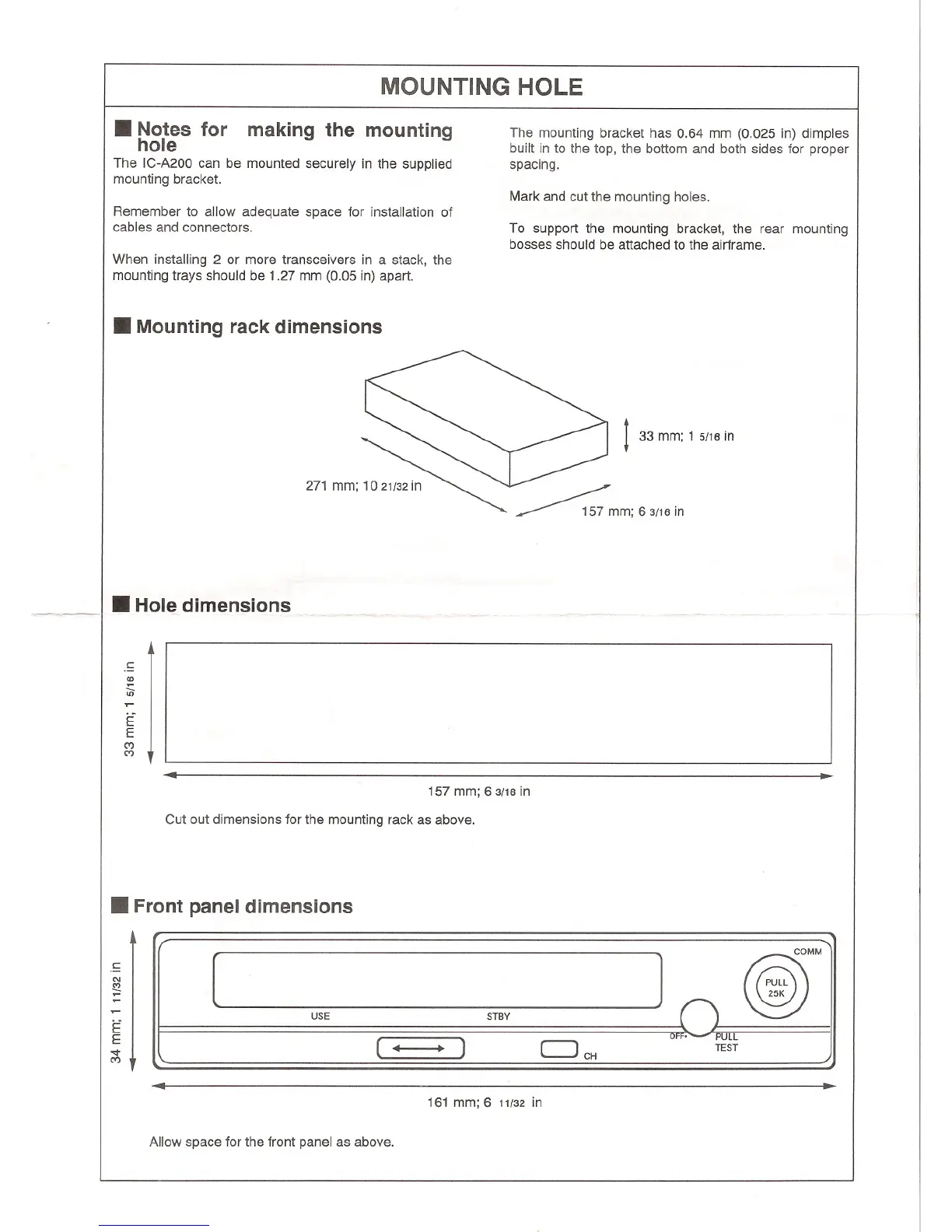
MOUNTING HOLE
.Notes for making the mounting
hole
The IC-A200 can be mounted securely in the supplied
mounting bracket.
The mounting bracket has 0.64 mm (0.025 in) dimples
built in to the top, the bottom and both sides for proper
spacing.
Mark and cut the mounting holes.
Remember to allow adequate space for installation of
cables and connectors.
To support the mounting bracket, the rear mounting
bosses should be attached to the airframe.
When installing 2 or more transceivers in a stack, the
mounting trays should be 1.27 mm (0.05 in) apart.
.Mounting rack dimensions
271 mm; 10 21132in
t 33 mm; 1 5/16in
""'-'k-
.Hole dimensions
.~
<0
in
E
E
C')
C')
.
157 mm; 63/16 in
Cut out dimensions for the mounting rack as above.
.Front panel dimensions
]
USE
STBY
( . )
c:JCH
Off. -- POl1.~
TEST
161 mm; 6 11/32 in
Allow space for the front panel as above.
. I II
[
:: I II
E
E
'oot
C')
, ....
4