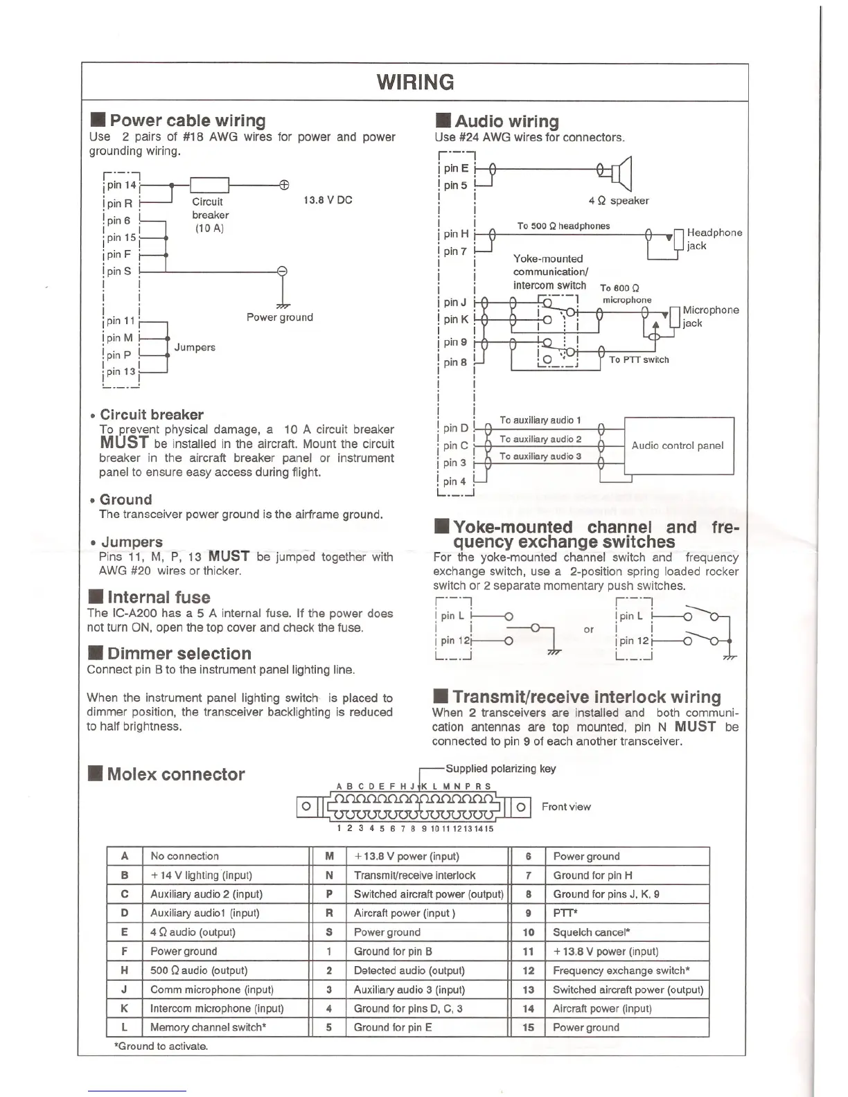
WIRING
.Power cable wiring
Use 2 pairs of #18 AWG wires for power and power
grounding wiring.
r'-'J
jpin14' ~
ipin R P- Circuit
!pin 6 ~ breaker
I .
15
i I (10 A)
ipin I
ipin F i
!pinS f
I I
i i
i i
iPin11
§
'
ipin M '
i .
P
, Jumpers
.pin ,
I .
13
1
jPln I
~ !
13.8 V DC
Power ground
. Circuit breaker
To JJreventphysical damage, a 10 A circuit breaker
MUST be installed in the aircraft, Mount the circuit
breaker in the aircraft breaker panel or instrument
panel to ensure easy access during flight.
.Ground
The transceiver power ground is the airframe ground.
. Jumpers
Pins 11, M, P, 13 MUST be jumped together with
AWG #20 wires or thicker.
.Internal fuse
The IC-A200has a 5 A internal fuse. If the power does
not turn ON, open the top cover and check the fuse.
.Dimmerselection
Connect pin B to the instrument panel lighting line.
When the instrument panel lighting switch is placed to
dimmer position, the transceiver backlighting is reduced
to half brightness.
.Audio wiring
Use #24 AWG wires for connectors.
r'-'J
!pin E r-e
!pin 5 !-f
I I
i i
!. LJ To 500 Q headphones
!pin H ,
!pin 7 ,
I I
! i
I I
ipinJ i
ipinK!
I I
ipin9 !
!pin8 !
! !
I I
i i
i i
!pinD ~
I .
C
I
i pin I
ipin3 r
!pin4 ~
L I
4 Q speaker
~n Headphone
~jaCk
Yoke-mounted
communicationl
intercom switch
,
To800Q
microphone
Microphone
jack
\
: i
, n
!~
O
';'
L.: .J
To auxiliary audio 1
To auxiliary audio 2
To auxiliary audio 3
Audio control panel
.Yoke-mounted channel and fre-
quency exchange switches
For the yoke-mounted channel switch and frequency
exchange switch, use a 2-position spring loaded rocker
switch or 2 separate momentary push switches.
r'-'J r'-'J
ipinL i---o ipin L ~
~
i i or i i
ipin 12r o~ !pin12r-o
L I L I
.Transmit/receive interlock wiring
When 2 transceivers are installed and both communi-
cation antennas are top mounted, pin N MUST be
connected to pin 9 of each another transceiver.
.Molex connector
Supplied polarizing key
ABC D E F H J JK L M N P R S
o
1 2 3 4 5 6 7 8 9 1011 12131415
o
Front view
*Ground to activate.
A No connection M
+ 13.8 V power (input)
6
Power ground
B
+ 14 V lighting (input)
N
Transmit/receive interlock
7
Ground for pin H
C
Auxiliary audio 2 (input)
P
Switched aircraft power (output)
8
Ground for pins J, K, 9
D
Auxiliary audi01 (input)
R
Aircraft power (input)
9
PTT*
E
4 Q audio (output)
S
Power ground
10
Squelch cancel*
F
Power ground
1
Ground for pin B
11
+ 13.8 V power (input)
H
500 Qaudio (output)
2
Detected audio (output)
12
Frequency exchange switch*
J
Comm microphone (input)
3
Auxiliary audio 3 (input)
13
Switched aircraft power (output)
K
Intercom microphone (input)
4
Ground for pins D, C, 3
14
Aircraft power (input)
L
Memory channel switch*
5
Ground for pin E
15
Power ground