3 - 1
SECTION 3 DISASSEMBLY INSTRUCTIONS
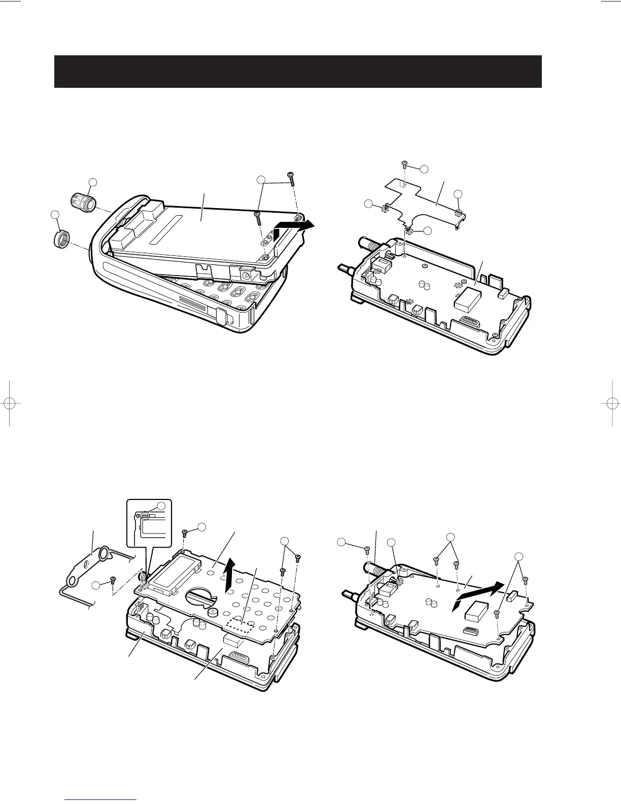
1 REMOVING THE CHASSIS PANEL
q Remove 1 knob,
B
, and unscrew 1 nut,
A
.
w Unscrew 2 screws
C
(
2 × 10 mm, black).
e Remove the chassis panel in the direction of the arrow.
2 REMOVING THE LOGIC UNIT
q Remove the sealing rubber.
w Unsolder 1 point,
D
, to separate a SENSOR control.
e Unscrew 4 screws
E
(2 × 4 mm, silver).
r Unplug J1 to separate LOGIC unit and RF unit.
t Remove the LOGIC unit in the direction of the arrow.
3 REMOVING THE SHIELD PLATE
q Unsolder 3 points,
F
, to separate the shield plate
and RF unit.
w Unscrew 1 screw
G
(2 × 4 mm, silver).
4 REMOVING THE RF UNIT
q Unsolder 1 point,
H
, to separate the [ANT] plug.
w Unscrew 5 screws
I
(2 × 4 mm, silver), to separate
the RF unit.
e Remove the RF unit in the direction of the arrow.