4 - 2
4-1-5 AF CIRCUIT (RF UNIT)
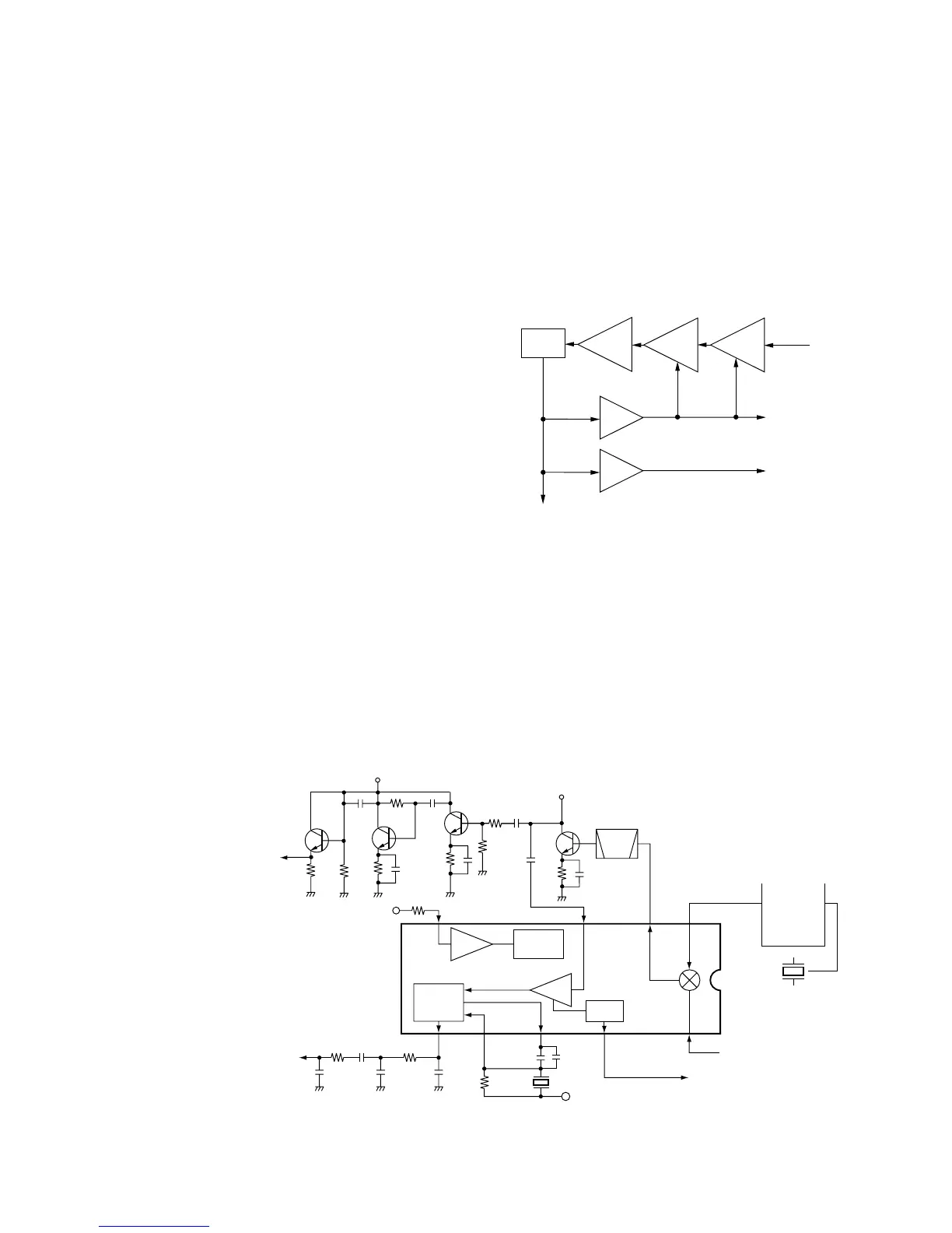
The AF amplifier circuit amplifies the demodulated AF sig-
nals to drive a speaker.
AF signals from the AM detector (Q18; While in AM mode)
or IF IC (IC1, pin 9; While in FM mode) are applied to the
AM/FM switch (IC2, pin 6 or 7). The output signals from pin
1 are applied to the AF amplifier (IC510, pin 6), and then
pass through the low-pass filter (IC510, pins 2, 1). The fil-
tered signals are amplified at the OP-amplifier (IC14), and
are then applied to the power amplifier (IC6, pin 4) to obtain
the specified audio level after being passed through the
electric volume (IC505, pins 1, 2). The amplified AF signals
are applied to the internal speaker (SP1) via the [EXT SP]
jack (J2) when no plug is connected to the jack.
4-1-6 SQUELCH CIRCUIT (RF AND LOGIC UNITS)
A squelch circuit cuts out AF signals when no RF signals are
received. By detecting noise components in the AF signals,
the squelch switches the AF mute switch.
A portion of the 2nd IF signal from the 2nd IF amplifier (Q15)
is fed back to the IF IC (IC1, pin 5). The IF signal is ampli-
fied at the IF amplifier section in the IC, which then detects
the receiver signal strength at the RSSI section for conver-
sion into DC voltage.
The DC voltage is applied to the CPU (LOGIC unit; IC1, pin
3) via the “RSSI” signal after being amplified at the RSSI
amplifier (IC13).
The CPU analyzes the noise condition and outputs the con-
trol signal to the shift resistor (IC5). The shift resistor (IC5,
pin 14) outputs the squelch control signal via “AFC” line. The
signal is applied to the AF out control circuit (Q36, Q35) to
control the power amplifier (IC6) and cut the AF signal line.
4-1-7 AGC CIRCUIT (RF UNIT)
The AGC (Automatic Gain Control) circuit reduce signal fad-
ing and keeps the audio output level constant.
AF signals from the AM detector circuit (Q18) are converted
into DC voltage at the AGC amplifier circuits (Q14; for
1st/2nd IF amplifiers, Q10; for RF amplifier) by detecting the
driving current at the AM detector. The DC voltage from the
AGC amplifiers is applied to the 1st/2nd IF amplifiers (Q13,
Q15, Q16) and RF amplifier (Q11) to reduce the amplifier
gain when strong signals are received.