EasyManuals Logo
Home>Icom>Transceiver>IC-F11

Icom IC-F11 Service Manual

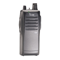
Icom IC-F11
78 pages
To Next Page IconTo Next Page
To Previous Page IconTo Previous Page
Page #43 background imageLoading...
Page #43 background image
2 - 1
SECTION 2 INSIDE VIEWS
• MAIN UNIT
Power amplifier
(Q1: 2SK2974)
Antenna switching circuit
D1: 1SV307
D9, D10: MA77
TOP VIEW BOTTOM VIEW
RF amplifier
(Q15: 3SK293)
VCO circuit
FM IF IC
(IC3: TA31136FN)
Low-pass filter circuit
(IC12,16: NJM12904V)
Expander IC
(IC15: BU4094BCFV)
TX/RX switch
(D3, D4: MA77)
Analog switch
(IC6: BU4066BCFV)
APC
(IC2: TA75S01F)
AF amplifier
(IC4: TA7368F)
1st mixer
(Q19: 2SB1132 R)
CPU
IC7: HD6433664A24FP
(F21/F21S/F21BR/
F21GM/F22/F22S)
: HD64F3664FP
(F22SR)
EEPROM
(IC11: HN58X2416TI)
D/A converter
(IC9: M62363FP-650C)
PLL reference oscillator
(X1: CR-671A)
Crystal filter
(FI1: FL-335)
PLL IC
(IC1: MB15A02PFV-1)
YGR amplifier
Q3: 2SC3585 R44
Q4: 2SC5107 O
Pre-drive
(Q2 : 2SK2973)
()
()
()

Other manuals for Icom IC-F11

Questions and Answers:

Question and Answer IconNeed help?

Do you have a question about the Icom IC-F11 and is the answer not in the manual?

Icom IC-F11 Specifications

General IconGeneral
BrandIcom
ModelIC-F11
CategoryTransceiver
LanguageEnglish

Related product manuals