5 - 5
1
1
2
3
1
2
1
• Operating frequency:
470.000 MHz
A
469.550 MHz B
467.725 MHz C
446.00625 MHz D
• High/Low switch : Low
• Connect the RF power meter or 50 Ω
dummy load to the antenna connector*
1
.
• Transmitting
• Operating frequency:
440.000 MHz
A
462.550 MHz B, C
446.00625 MHz D
• High/Low switch : High
• Transmitting
• High/Low switch : Low2
• Transmitting
• High/Low switch : Low1
• Transmitting
• Operating frequency:
455.000 MHz
A
466.050 MHz B
465.138 MHz C
• High/Low switch : Low1
• Channel spacing : Wide
• Connect the audio generator to the
[MIC] jack and set as:
1.0 kHz/150 mVrms
• Set the FM deviation meter as:
HPF : OFF
LPF : 20 kHz
De-emphasis : OFF
Detector : (P±P)/2
• Transmitting
• Operating frequency:
455.000 MHz
A
466.050 MHz B
465.138 MHz C
446.00625 MHz D
• Channel spacing : Narrow
• Transmitting
• Operating frequency:
455.000 MHz
A
466.050 MHz B
465.138 MHz C
446.00625 MHz D
• High/Low switch : Low1
• No audio applied to the [MIC] jack.
• DTCS code : 007
• Transmitting
REFERENCE
FREQUENCY
[TXF]
OUTPUT
POWER
[POWER(Hi)]
[POWER(L2)]
[POWER(L1)]
FM
DEVIATION
(Wide)
[MOD W]
(
A
,
B
,
C
only)
(Narrow)
[MOD N]
DTCS WAVE
FORM
[DTCS BAL]
Top
panel
Top
panel
Top
panel
Top
panel
Loosely couple a frequnecy
counter to the antenna connec-
tor*
1
.
Connect an RF power meter to
the antenna connector*
1
.
Connect an FM deviation meter
to the antenna connector*
1
through the attenuator.
Connect an FM deviation meter
with an oscilloscope to the
antenna connector*
1
through an
attenuator.
470.0000 MHz
A
469.5500 MHz B
467.7250 MHz C
446.0062 MHz D
4.0 W A, C
2.0 W B
1.5 W D
2.0 W A, B, C
1.5 W D
1.0 W
±4.10 kHz
(except
D)
±2.10 kHz
ADJUSTMENT ADJUSTMENT CONDITION
MEASUREMENT
VALUE
UNIT
LOCATION
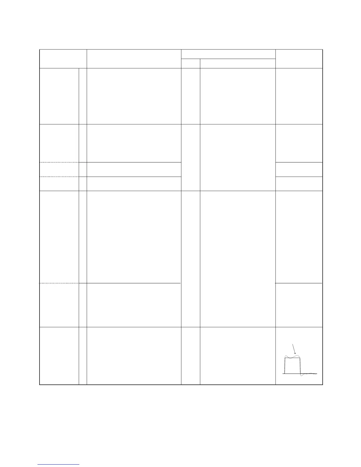
5-3 SOFTWARE ADJUSTMENT
Select an operation using [↑] / [↓] keys, then set specified value using [←] / [→] keys on the connected computer keyboard.
A: [F21], [F21S], [F22] and [F22S], B: [F21BR], C: [F21GM], D: [F22SR]
*
1
In case of IC-F22SR, instead of the antenna connector, connect to the J7 as shown page 5-3.

 Loading...