4 - 4
4-4 FFSK CIRCUIT DESCRIPTION
4-5-1 GENERAL
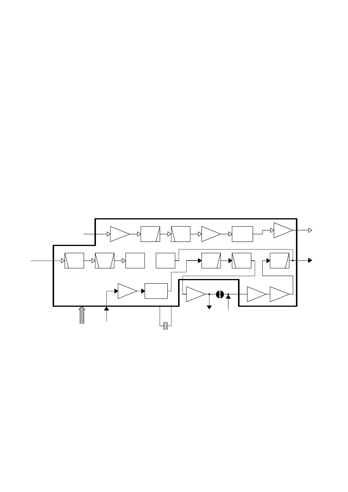
IC9 is the compounder IC which is controlled by serial data
bus line (“TRD”, “MSKE”, “DIN”, “SCK”, “APST”, “REGS1”,
“REGS2”, “RTM”, “RDT”, “FCLR” signals) from the CPU.
The IC is composed of FFSK transmitting and receiving cir-
cuits, data register circuits, transmitting and receiving data
buffer circuits, and so on.
X4 is oscillated 3.58 MHz reference signal to the IC9.
4-4-2 DECODEING CIRCUIT
The input signal from the FM IC (IC3, pin 9) via the “DSIN”
signal is applied to the compounder IC (IC9, pin 5), and is
then detected bit synchronization detection within 16 bit.
4-4-3 ENCODEING CIRCUIT
The FFSK signal is made by serial data bus line signals, and
is then output from the compounder IC (IC9, pin 6).
In case of the FFSK signal is used for the PM modulation,
the FM/PM switch (IC26) is changed to pin 6.
In case of the FFSK signal is used for the FM modulation,
the FM/PM switch (IC26) is changed to pin 7.
The output signal from IC26, pin 1 is applied to the the buffer
amplifier (IC8, pins 1, 4), and is applied to the D/A convertor
IC (IC13, pins 21, 22). The signal is applied to the modula-
tion circuit (Q12, D7, D8).
 Loading...