3 - 1
SECTION 3 DISASSEMBLY INSTRUCTIONS
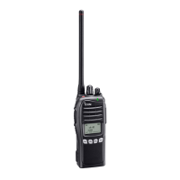
1 Removing the chassis panel
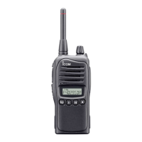
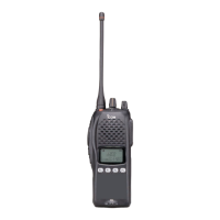
2 Removing the shield plate
3 Removing the MAIN unit
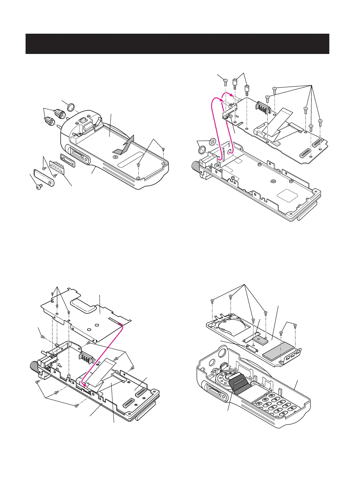
4 Removing the FRONT unit
q Remove 2 knobs
A
, and unscrew 1 nut
B.
w Unscrew 1 screw C (ICOM screw), and 2 screws
D
(2 ×
4 mm, black) from the 9-pin connector.
e Unscrew 2 screws
E (2 × 8 mm, silver) from the chassis.
r Ta ke off the chassis in the direction of the arrow.
q Unplug the flexible cable from J1 on the FRONT unit to
separate the chassis.
w Ta ke off the flexible cable in the direction of the arrow.
e Unscrew 10 screws
F (2 × 3 mm, black) to separate the
shield plate.
q Unsolder 1 point
G at the antenna lead.
w Unscrew 2 nuts
H.
e Unscrew 6 screws
I
(2 × 4 mm, silver), and 2 screws
J
from the MAIN unit.
r Ta ke off the MAIN unit in the direction of the arrow.
q Unplug the LCD flexible cable from J2 on the FRONT unit
to separate the front panel.
w Unscrew 6 screws
K
(2 × 3.5 mm, silver) from the FRONT
unit.
e Unsolder the leads of speaker.
 Loading...