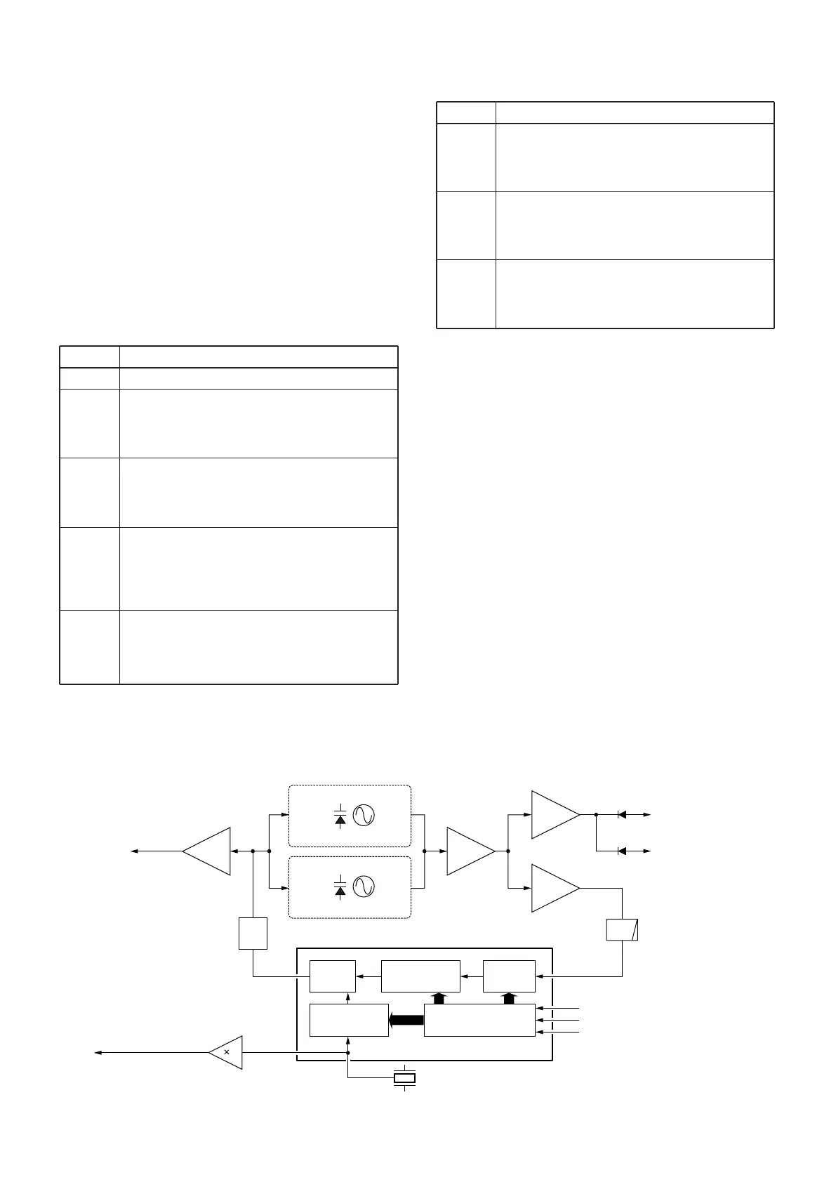
4-3-2 VCO CIRCUIT (MAIN UNIT)
The VCO circuit contains a separate RX VCO (Q14, D19,
D20) and TX VCO (Q13, D16, D17). The oscillated signal
is amplified at the buffer amplifiers (Q10, Q12) and is then
applied to the T/R switch (D14, D15). Then the receive 1st
LO (Rx) signal is applied to the 1st mixer (Q3) and the
transmit (Tx) signal to the pre-drive amplifier circuit (Q9).
A portion of the signal from the buffer amplifier (Q12) is fed
back to the PLL IC (IC4, pin 8) via the buffer amplifier (Q11)
as the comparison signal.
LINE
VCC
+5V
S5V
R5V
T5V
DESCRIPTION
The voltage from the connected battery pack.
Common 5 V converted from the VCC line at
the +5 regulator circuit (IC9). The output voltage
is supplied to the fast switch (IC17), buffer
amplifiers (IC16, IC18) and so on.
Common 5 V converted from the VCC line at
the S5 regulator circuit (Q23–Q25). The output
voltage is supplied to the ripple filter (Q17), PLL
IC (IC4), FRONT unit, etc.
Receive 5 V converted from the S5V line at the
R5 regulator circuit (Q22). The output voltage
is supplied to the tripler (Q19), FM IF IC (IC1),
IF amplifier (Q4), VCO switch (Q15, Q16), 1st
mixer (Q3), etc.
Transmit 5 V converted from the S5V line at the
T5 regulator circuit (Q21). The output voltage
is supplied to the pre-drive (Q9), APC amplifier
(IC2).
LINE
VCC
CPU5
S5V
DESCRIPTION
Same voltage as VCC line on the MAIN unit is
applied to the FRONT unit via the J401, pins 1,
2 (FRONT unit). The voltage is supplied to the
[PWR] switch controller (Q401, Q402).
Same voltage as +5V line on the MAIN unit is
applied to the FRONT unit via the J401, pin 4
(FRONT unit). The voltage is supplied to the
CPU (IC401), reset IC (IC408), etc.
Same voltage as S5V line on the MAIN unit is
applied to the FRONT unit via the J401, pin 5
(FRONT unit). The voltage is supplied to the mic
mute circuit (IC406), etc.
Shift register
Prescaler
Phase
detector
Loop
filter
Programmable
counter
Programmable
divider
X2
15.3 MHz
1
Buffer
Q11
Buffer
Q18
Buffer
Q10
Buffer
Q12
9
10
11
SCK
SO
PLST
to transmitter circuit
to 1st mixer circuit
D14
D15
5
8
Q14, D17
TX VCO
Q13, D16
RX VCO
IC4 MB15A02
3
45.9 MHz 2nd LO
signal to the FM IF IC
(IC1, pin 2)
Tripler
Q34
2
"LVIN" signal to the CPU
(FRONT unit; IC401, pin 49)
LPF
• PLL CIRCUIT
4-4 POWER SUPPLY CIRCUIT
4-4-1 MAIN UNIT VOLTAGE LINE
4-4-2 FRONT UNIT VOLTAGE LINE
4 - 4

 Loading...