Oscillo--
AF
Signal
Millivolt
scope
meter
Generator
SP
JACK
EXT.
RF
Voltmeter
SP
0
Power
IC
1
Supply
(MAIN)
(8.4V)
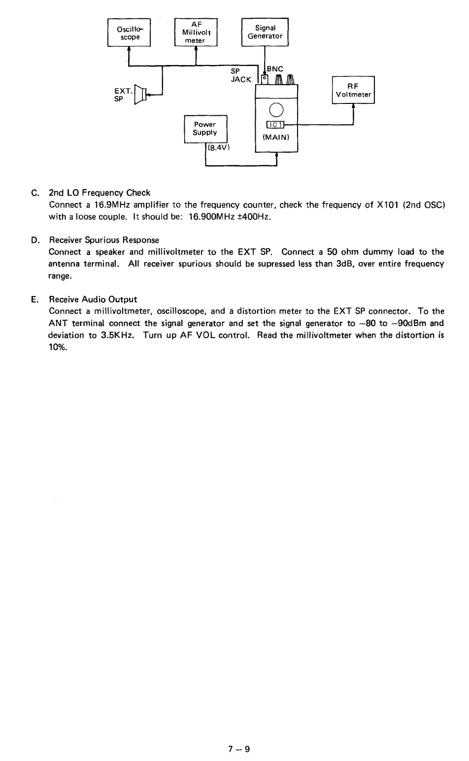
C.
2nd
LO
Frequency Check
Connect a 16.9MHz amplifier
to
the
frequency counter, check
the
frequency
of
X101 (2nd OSC)
with a loose couple. It should be: 16.900MHz ±400Hz.
D.
Receiver Spurious Response
Connect a speaker and
millivoltmeter
to
the
EXT
SP.
Connect a
50
ohm dummy load
to
the
antenna terminal.
All
receiver spurious should be supressed less than 3dB, over entire frequency
range.
E.
Receive Audio
Output
Connect a millivoltmeter, oscilloscope, and a distortion meter
to
the EXT
SP
connector. To
the
ANT terminal connect
the
signal generator and set
the
signal generator
to
-80
to
-90d8m
and
deviation
to
3.5KHz. Turn up AF VOL control. Read
the
millivoltmeter when
the
distortion
is
10%.
7-9
 Loading...