4 - 5
Pin
NO.
Port name Description
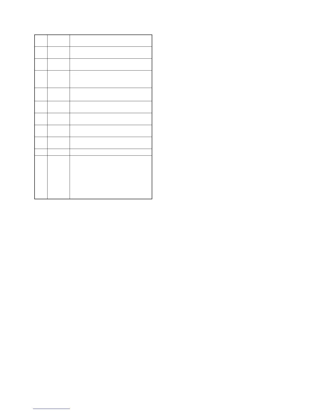
71 DSC
Input port for the [DSC] key (LOGIC BOARD; S7).
Low: [DSC] key is pushed.
72 PA
Input port for the [PA] key (LOGIC BOARD; S6).
Low: [PA] key is pushed.
73 CH/WX
Input port for the [CH/WX] key (LOGIC
BOARD; S5).
Low: [CH/WX] key is pushed.
74 SCAN
Input port for the [SCAN] key (LOGIC BOARD; S4).
Low: [SCAN] key is pushed.
75 CH16
Input port for the [16] key (LOGIC BOARD; S3).
Low: [16] key is pushed.
76 DOWN
Input port for the [
Z
] key (LOGIC BOARD; S2).
Low: [
Z
] key is pushed.
77 UP
Input port for the [
Y
] key (LOGIC BOARD; S1).
Low: [
Y
] key is pushed.
138 DIM
Outputs dimmer control signal to the LCD control
circuit (LOGIC BOARD; Q2, Q3).
139 BEEP Outputs beep signal to the AF amplifi er (IC9, pin 1).
141 DS/BPF
• While transmitting:
Outputs DSC encode signal as "DSENC"
to the LPF (IC8, pin 5) via the buffer amplifi er
(LOGIC BOARD; IC5, pins 1, 3).
• While receiving:
Outputs tuning signal as "BPFV" to the
tunable BPFs (D25–D28) via buffer amplifi er
(LOGIC BOARD; IC5, pins 5, 7).
4-7 PORT ALLOCATIONS (continued)