87
10
CONNECTIONS AND MAINTENANCE
MB-132 installation ■
An optional MB-132 f l u s h m o u n t is available for mounting the
transceiver to a flat surface, such as an instrument panel.
KEEP the transceiver and microphone at least 1 meter
away from your vessel’s magnetic navigation compass.
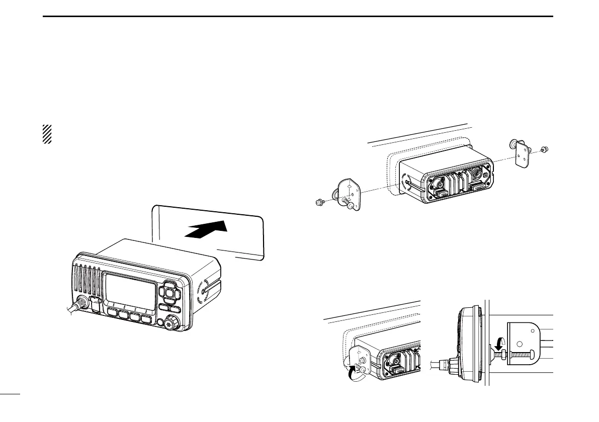
Using the template on page 94, carefully cut a hole into q
the instrument panel, or wherever you plan to mount the
transceiver.
Slide the transceiver through the hole, as shown below. w
Attach the clamps on either side of the transceiver with 2 e
M5 × 8 mm supplied bolts.
•Makesurethattheclampsalignparalleltothetransceiverbody.
Tighten the end bolts on the clamps (clockwise) so that the r
clamps press firmly against the inside of the instrument
control panel.
Tighten the locking nuts (counterclockwise) so that the trans- t
ceiver is securely mounted in position, as shown below.
Connect the antenna and power cable, then return the in- y
strument control panel to its original place.