4 - 6
MAIN UNIT ADJUSTMENT (Continued)
POWER SET
(HF BAND,
AC 200 V,)
(AC 100 V)
[USA], [EUR]
only
(50 MHz,
AC 200 V)
P
O
METER SET
(HF bands)
(50 MHz band)
SWR
METER SET
V
D
METER SET
ADJUSTMENT
ADJUSTMENT ADJUSTMENT CONDITION
MEASUREMENT
VALUE
POINT
UNIT LOCATION UNIT ADJUST
1
2
3
1
2
3
1
1
2
1
1
1
• Input AC voltage : 200 V
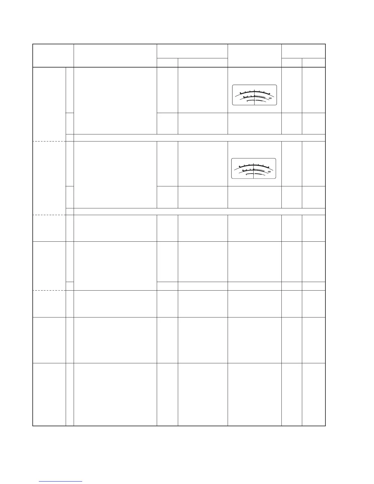
• METER-1 : [P
O] scale
• METER-2 :
[ALC] scale
• Exciter frequency : 21.1 MHz
• Mode : RTTY
• Transmitting
• Input AC voltage : 100 V
• Set ALC adj1 to max. counter-
clockwise.
• Exciter frequency : 14.1 MHz
• Mode : RTTY
• Transmitting
• Input AC voltage : 200 V
• Exciter frequency : 50.2 MHz
• Mode : RTTY
• Transmitting
• Turn ALC adj1 to max. counter-
clockwise.
• METER-1 : [P
O] scale
• Exciter frequency : 21.1 MHz
• Mode : RTTY
• Transmitting
• Connect the RF power meter to
the [ANT1] connector.
• Exciter frequency : 50.2 MHz
• Transmitting
• Connect a 100 Ω dummy load to
[ANT1] connector.
• METER-2 :
[SWR] scale
• Exciter frequency : 14.1 MHz
• Mode : RTTY
• Power : 1 kW
• Transmitting
• METER-2 : [V
D] scale
• Connect the DC voltmeter
between the “HV” line and the
“GND” line of the power supply
unit.
Controller
REAR
panel
Controller
REAR
panel
REAR
panel
REAR
panel
Controller
Controller
Controller
Controller
[METER-2]
Connect the RF
power meter to the
[ANT1] connector.
[METER-2]
Connect the RF
power meter to the
[ANT1] connector.
Connect the RF
power meter to the
[ANT1] connector.
Connect the RF
power meter to the
[ANT1] connector.
[METER-1]
[METER-1]
[METER-2]
[METER-2]
Set [ALC] meter to
center as below:
1050 W
Set [ALC] meter to
center as below:
520 W
1020 W
1050 W
1050 W
Same power as the
RF power meter.
SWR 2
Same voltage as the
DC
voltmeter.
REAR
panel
MAIN
REAR
panel
MAIN
MAIN
REAR
panel
MAIN
MAIN
MAIN
MAIN
ALC adj1
R4
ALC adj1
R6
R5
ALC adj1
R26
R240
R31
R197