4 - 8
MAIN UNIT ADJUSTMENT (Continued)
ID ALC
I
D METER
ADJUSTMENT
ADJUSTMENT ADJUSTMENT CONDITION
MEASUREMENT
VALUE
POINT
UNIT LOCATION UNIT ADJUST
1
2
3
4
1
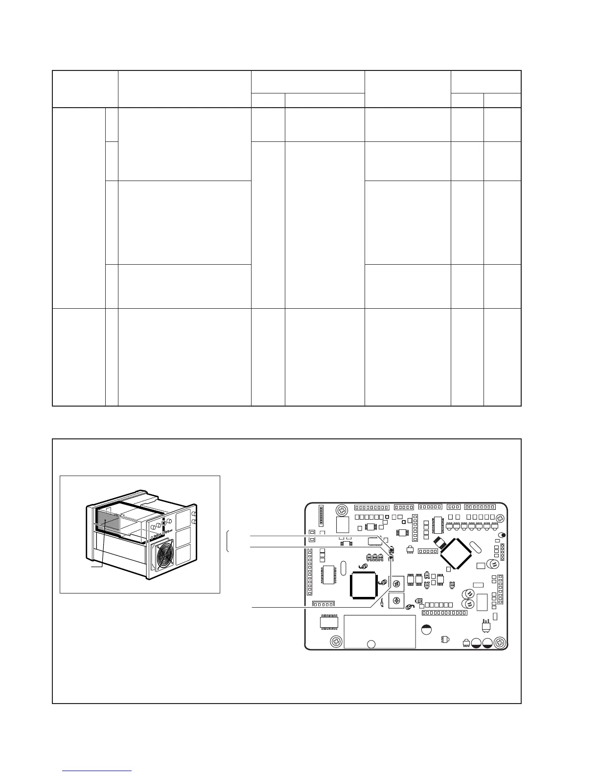
• Connect a DC ammeter to the
“HV” line between power supply
unit and PA unit.
• METER-1 : [I
D] scale.
• Exciter frequency : 14.1 MHz
• Mode : RTTY
• Transmitting
• Connect a load-resistor between
“HV” line and “GND” line on
power supply unit.
• Transmitting
• Disconnect a DC ammeter, and
then connect a DC ammeter to
the “HV” line between power sup-
ply unit and a load-resistor.
• Disconnect a DC ammeter, and
then connect a DC ammeter to
the “HV” line between power sup-
ply unit and PA unit.
• Connect a DC ammeter to the
“HV” line between power supply
unit and PA unit.
• METER-1 : [I
D] scale.
• Exciter frequency : 14.1 MHz
• Mode : RTTY
• Transmitting
Controller
Front
panel
Controller
[METER-1]
Ammeter
[METER-1]
Set [I
D] meter to a half
value of connecting
ammeter.
38 A
9.7 – 10.3 A
34.7 – 35.3 A
The same value of the
ammeter.
MAIN
Exciter
MAIN
MAIN
R22
RF
power
The
load-
resistor
R15
R22