4-1-7
AF
AMPLIFIER CIRCUIT
(LOGIC UNIT)
The
AF
amplifier circuit,
Including an AF mute
switch,
amplifies the
demodulated
signals to
drive a speaker.
The
demodulated
AF
signals (“DETO"
signals) from the FM
IF
IC
(IC
101)
on the 2F
unit are
applied
to the
drive
amplifier
(Q12)
though the
bandpass filter (C44,
C45).
The
bandpass
filter suppresses
subaudible tones and
higher
noise
signal
components.
The
amplified signals from
Q12
pass through the AF mute
switch
(Q10)
and
are then applied to the
AF
volume
control
on the
1
F
unit via
the “AF" signal
line.
4-1-8
AF
POWER
AMPLIFIER CIRCUIT
(2F
UNIT)
The
AF
signals from the AF volume
control (“AFV” signals)
are
amplified at
the AF power
amplifier
IC (IC151).
The
amplified AF
signals are applied to
the loud speaker via the
external speaker
jack (1
F
unit
J902).
4-1-9
NOISE
SQUELCH UNIT
(2F
UNIT)
A
noise squelch
circuit cuts out AF signals when
no
RF
signal is
received.
By
detecting noise components in the
AF
signals, the
squelch
circuit
switches the AF mute switch.
Some
of the noise
components in
the
AF signals from
the
FM IF IC (IC101
pin
9)
are applied
to
the
active filter section
(IC101
pins
7,
8).
The
variable register (R504) adjusts the
active
filter input level.
The
active filter
section amplifies noise components with
frequencies of
20
kHz and
above. The
filtered
signals are
rectified at
the noise detector
section and converted into
“NOISE”
(pulse
type) signals at the noise comparator
section. The “NOISE”
signal is applied to the CPU (LOGIC
unit
IC1 pin
12).
The
CPU detects
the signal
level from the number of
the
pulses,
and outputs an “MM/RM"
signal from pin 44. This
signal
controls the AF mute
switch
(01
0)
to
cut the AF
signal line.
4-2
TRANSMITTER
CIRCUITS
4-2-1
MICROPHONE AMPLIFIER
CIRCUIT
(LOGIC
AND 2F UNIT)
The microphone
amplifier circuit amplifies audio
signals
with
+6
dB/octave pre-emphasis from the
microphone
to
a level
needed for the
modulation circuit.
The AF
signals from the
built-in condenser microphone
(LOGIC
unit
MCI),
or from the [MIC]
jack via the “EXT MIC"
line are applied to the
limiter amplifier
(LOGIC
unit
1C12
pin
3)
which has +6
dB/octave pre-emphasis
characteristics.
The amplified AF
signals pass though the splatter filter
(IC12
pins 5-7). The filtered signals
are
applied to
frequency deviation pots (2F
unit
R308
for VHF, R314
for
UHF)
and are then
applied to the modulation
circuit on
the
DUALVCO
board.
Q32 on the LOGIC
unit Is the PTT
control circuit
and
outputs a “High”
signal
to
the CPU when
transmitting.
4-2-2
MODULATION CIRCUIT
(DUAL VCO
BOARD)
The modulation
circuit modulates
the VCO
oscillating
signal
(RF
signal) using the microphone audio
signals.
The “VMOD” signals change the
reactance of
a
diode
(D304)
to modulate the oscillated signal
at
the VHF-VCO
circuit
(0304,
0305,
D303).
The “UMOD"
signals are applied to the UHF-VCO circuit via
the
“USHIFT”
line. The applied
signals
change the
reactance
of
a
diode
(D302)
to modulate the oscillated
signal at the UHF-VCO
circuit
(0301
,
0302,
D301).
The VCO output is
buffer-amplified
at 0306
and then
applied
to the >band
switch
(D351, D352)
via the
LO
amplifiers
(0852,
0351).
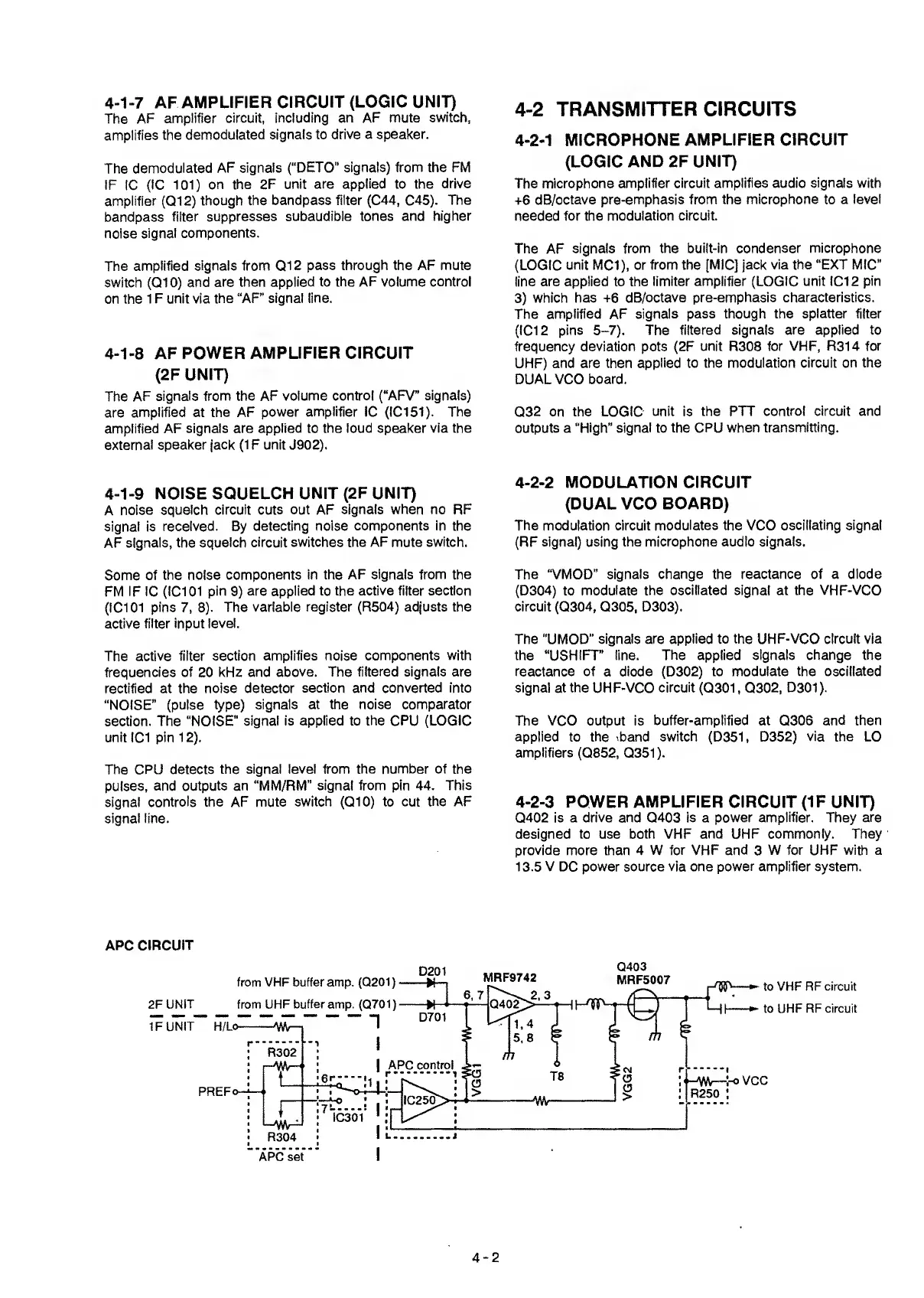
4-2-3
POWER
AMPLIFIER
CIRCUIT
(IF
UNIT)
0402 is a
drive
and 0403 is a power
amplifier.
They
are
designed
to
use
both
VHF
and
UHF
commonly. They
provide more
than 4
W for VHF and
3
W for UHF with a
1 3.5 V DC power source via one
power amplifier
system.
APC CIRCUIT
4-2
 Loading...