9
4
CONNECTIONS AND MAINTENANCE
New2001
1
2
3
4
5
6
7
8
9
10
11
12
13
14
15
16
■ Antenna
A key element in the performance of any communication sys-
tem is the antenna. Ask your dealer about antennas and the
best place to mount them.
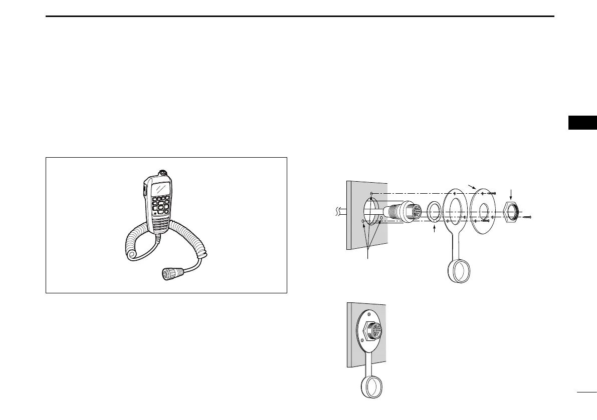
■ Microphone installation
The HM-195 should be connected to the transceiver using
the supplied OPC-1540 connection cable. The cable is used
to operate from a longer distance. The cable connector can
also be installed as a built-in plug on a cabinet or wall.
To operate from even longer distances, the optional 6 meter
long OPC-1541 extension cable can be used between the
transceiver and the OPC-1540. Up to two OPC-1541 can be
added.
D Installation
q Insert the OPC-1540 cable connector into the command
microphone jack, and tighten the nut.
w To use the cable connector as a wall socket, install it as
described to the right.
e Using the mounting base as a template, carefully mark the
holes where the cable and three screws will be fastened.
r Drill holes at these marks.
t Install the mounting base using the supplied screws, as
shown below.
Gasket
Cap
Screw holes
(approximately 2 mm;
3
⁄32˝ (d))
y The completed installation should look like this.