EasyManua.ls Logo

ICP A Series User Manual

ICP A Series
74 pages
To Next Page IconTo Next Page
Page #1 background imageLoading...
Page #1 background image
. 440 01 4542 00 11/18/19
INSTALLATION INSTRUCTIONS
Single--Stage, 35--in. (889 mm) Tall
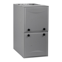
High Efficiency Condensing Gas Furnace
N92ESN
(Series A)
NOTE: Read the entire instruction manual before starting the installation.
SECTIONS
SAFETY CONSIDERATIONS 4.........................
INTRODUCTION 5...................................
CODES AND STANDARDS 6...........................
ELECTROSTATIC DISCHARGE (ESD) PRECAUTIONS 7...
ACCESSORIES 7.....................................
LOCATION 7........................................
AIR FOR COMBUSTION AND VENTILATION 8..........
CONDENSATE TRAP 11...............................
CONDENSATE DRAIN 14.............................
INSTALLATION 16...................................
AIR DUCTS 23.......................................
GAS PIPING 25......................................
ELECTRICAL CONNECTIONS 26.......................
VENTING 31........................................
START-- UP, ADJUSTMENT, AND SAFETY CHECK 53......
SERVICE AND MAINTENANCE PROCEDURES 61........
SEQUENCE OF OPERATION 71........................
PARTS REPLACEMENT GUIDE 73......................
Use of the AHRI Certified TM Mark indicates a
manufacturer’s participation in the program.
For verification of certification for individual
products, go to www.ahridirectory.org .
Portions of the text and tables are reprinted from current edition of
NFPA 54/ANSI Z223.1, with permission of National Fire
Protection Association, Quincy, MA 02269 and American Gas
Association, Washington DC 20001. This reprinted material is not
the complete and official position of the NFPA or ANSI on the
referenced subject, which is represented only by the standard in its
entirety.
TABLES
Loose Parts Bag 6.....................................
Minimum Clearances to Combustible Materials 5.............
Minimum Free Area Required 9..........................
Minimum Space Volumes 9..............................
Opening Dimensions 19................................
Filter Size Information 20...............................
Air Delivery CFM 24...................................
Maximum Capacity of Pipe 25...........................
Electrical Data 27......................................
Vent Termination Kit for Direct Vent (2--Pipe) System 34.......
Maximum Equivalent Vent Length 43......................
Deductions from Maximum Equivalent Vent Length 43........
Maximum Allowable Exposed Vent Lengths Insulation 47......
Hangar Spacing 49.....................................
Combustion--Air Vent Pipe, Fitting & Cement Material.. 51.....
Altitude Derate Multiplier for U.S.A. 54....................
Blower Off Delay Setup Switch 56........................
Orifice Size and Manifold Pressure 58.....................
Gas Rate 61..........................................
Question and Answer IconNeed help?

Do you have a question about the ICP A Series and is the answer not in the manual?

ICP A Series Specifications

General IconGeneral
EfficiencyUp to 96% AFUE
Fuel TypeGas
Heating ElementsNot applicable
Thermocouple TypeNot applicable
Exterior DimensionsVaries by model
Interior DimensionsNot applicable
WeightVaries by model

Summary

Safety Considerations

Introduction

Codes and Standards

Electrostatic Discharge (ESD) Precautions Procedure

Accessories

Location

Air for Combustion and Ventilation

Introduction

Basic introduction to air for combustion and ventilation requirements.

Direct Vent (2-pipe) Applications

Requirements for direct-vent (2-pipe) furnace installations.

Ventilated Combustion Air Applications

How to supply combustion air from ventilated spaces.

Non-Direct Vent (1-pipe) System

Requirements for non-direct vent (1-pipe) furnace installations.

Outdoor Combustion Air Method

Standard Method

Procedures for ensuring adequate air for combustion, ventilation, and dilution.

Known Air Infiltration Rate Method

Method for determining air supply based on measured infiltration rates.

Combination of Indoor and Outdoor Air

Method combining indoor and outdoor air for combustion needs.

Condensate Trap

Condensate Trap - Upflow Orientation

Instructions for managing the condensate trap in the upflow furnace position.

Condensate Trap - Downflow Orientation

Steps for relocating the condensate trap for downflow furnace installation.

Horizontal Right Trap Configuration

Unconverted Factory Trap Configuration As Viewed in the Horizontal Left Orientation

Condensate Drain Connection

Upflow/Downflow Orientation

Routing condensate drain from the trap through the furnace casing in upflow/downflow positions.

For Right Side Condensate Drain

Detailed steps for connecting the condensate drain to the right side of the furnace.

For Left Side Condensate Drain Connection

Horizontal Orientation

Supply Air Connections

Return Air Connections

Side Return Air Inlet

Downflow Installation

Horizontal Installation

Filter Arrangement

Filter and Return Duct Sizing

Leveling Legs (If Desired)

Location Relative to Cooling Equipment

How to position the furnace relative to cooling coils to prevent condensation.

Platform Furnace Support

Guidelines for constructing a platform to support the furnace.

Suspended Furnace Support

Methods for suspending the furnace using threaded rod and angle iron.

Roll-Out Protection

Requirements for flame roll-out protection using sheet metal.

Gas Piping

Electrical Connections

J-Box Installation

BX Cable Installation in Furnace J-Box

24-V Wiring

Accessories

Venting

Special Venting Requirements for Installations in Canada

Specific venting requirements for installations within Canada, conforming to CSA B149 code.

Carbon Monoxide Poisoning Hazard

General

Venting Systems

Direct Vent / 2-Pipe System

How combustion air and flue products are handled in a two-pipe direct vent system.

Ventilated Combustion Air Systems

How combustion air is supplied from a ventilated space for the furnace.

Non-Direct Vent (1-pipe) System

How combustion air is drawn from the adjacent area in a single-pipe system.

Inside Corner Terminations

Locating the Vent Termination

General

General guidelines for locating vent terminations, considering performance and obstacles.

Direct Vent / 2-Pipe System

Specific termination requirements for direct vent (2-pipe) systems, including clearance and placement.

Ventilated Combustion Air

Non-Direct Vent / 1-Pipe System

Termination requirements for non-direct (1-pipe) vent systems.

Termination Requirements for the Provinces of Alberta and Saskatchewan

Specific vent termination rules for Alberta and Saskatchewan.

Size the Vent and Combustion Air Pipes

How to size vent and combustion air pipes based on furnace input and vent length.

Recommended Combustion Air Inlet Moisture Trap

Combustion Air and Vent Piping Insulation Guidelines

Configure the Furnace

Instructions on how to set up the furnace for vent pipe and combustion air connections.

Near Furnace Vent Connections

Vent Coupling and Adapter

How to use the vent coupling and adapter for connecting pipes to the furnace.

Installing the Vent Termination

Roof Terminations

Procedures for installing vent terminations through a roof.

Concentric Vent

How to install concentric vent terminations, including flashing and clearances.

Two-Pipe and Single-Pipe Terminations

Installation of two-pipe and single-pipe vent terminations, including hole cutting and pipe spacing.

Inducer Outlet Restrictor

USA

Approved materials for combustion-air and vent pipes in the USA.

CANADA

Approved materials for combustion-air and vent pipes in Canada.

Venting System Length Calculations

Start-Up, Adjustment, and Safety Check

General

Basic checks and procedures for furnace start-up and operation.

Prime Condensate Trap with Water

Step-by-step instructions to prime the condensate trap with water before operation.

Check Inlet Gas Pressure

Adjust Manifold Pressure

Adjust Temperature Rise

Adjust Cooling Airflow

Check Safety Controls

Checklist

A list of final checks to perform after installation and adjustments.

Service

LED Status Codes

Explanation of the LED status codes for diagnostics and troubleshooting.

Component Test

Procedure for running a self-test of furnace components to diagnose issues.

Service and Maintenance Procedures

General

General advice on furnace maintenance procedures.

Electrical Controls and Wiring

Information on electrical controls and proper wiring practices.

Troubleshooting

Retrieving Stored Fault Codes

How to access and interpret stored fault codes from the control board.

Component Self-Test

Instructions on how to perform the furnace's component self-test sequence.

Cleaning Burners and Flame Sensor

Blower Motor and Wheel Maintenance

Servicing Hot Surface Ignitor

Flushing Collector Box and Drainage System

Cleaning Heat Exchangers

Primary Heat Exchangers

How to clean the primary heat exchangers if they accumulate light dirt or dust.

Winterization

Troubleshooting Guide

Sequence of Operation

Heating

Step-by-step sequence of operation for the furnace during heating mode.

Cooling Mode

The sequence of operation when the furnace is used for cooling.

Continuous Blower Mode

How the furnace operates when the blower is set to run continuously.

Heat pump

Sequence of operation when the furnace is integrated with a heat pump system.

Component Self-Test

Instructions on how to perform the component self-test.

Parts Replacement Information Guide

Related product manuals