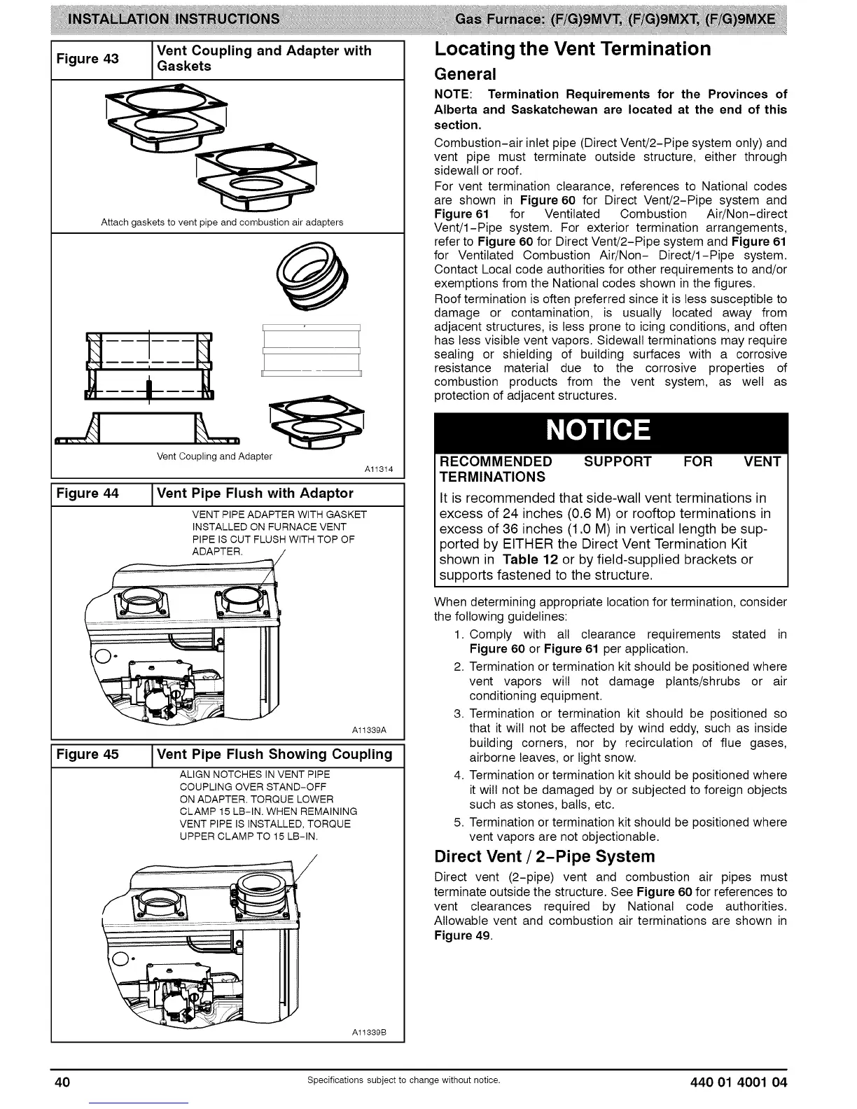
Figure 43
Vent Coupling and Adapter with
Gaskets
Attach gaskets to vent pipe and combustion air adapters
L
Vent Couplingand Adapter
Figure 44
Al1314
I Vent Pipe Flush with Adaptor
VENT PIPE ADAPTER WITH GASKET
INSTALLED ON FURNACE VENT
PIPE IS CUT FLUSH WITH TOP OF
ADAPTER.
Figure 45
A11339A
I Vent Pipe Flush Showing Coupling
ALIGN NOTCHES IN VENT PIPE
COUPLING OVER STAND-OFF
ON ADAPTER. TORQUE LOWER
CLAMP 15 LB-IN. WHEN REMAINING
VENT PIPE IS INSTALLED, TORQUE
UPPER CLAMP TO 15 LB-IN.
A11889B
Locating the Vent Termination
General
NOTE: Termination Requirements for the Provinces of
Alberta and Saskatchewan are located at the end of this
section.
Combustion-air inlet pipe (Direct Vent/2-Pipe system only) and
vent pipe must terminate outside structure, either through
sidewall or roof.
For vent termination clearance, references to National codes
are shown in Figure 60 for Direct Vent/2-Pipe system and
Figure 61 for Ventilated Combustion Air/Non-direct
Vent/I-Pipe system. For exterior termination arrangements,
refer to Figure 60 for Direct Vent/2-Pipe system and Figure 61
for Ventilated Combustion Air/Non- Direct/I-Pipe system.
Contact Local code authorities for other requirements to and/or
exemptions from the National codes shown in the figures.
Roof termination is often preferred since it is less susceptible to
damage or contamination, is usually located away from
adjacent structures, is less prone to icing conditions, and often
has less visible vent vapors. Sidewall terminations may require
sealing or shielding of building surfaces with a corrosive
resistance material due to the corrosive properties of
combustion products from the vent system, as well as
protection of adjacent structures.
RECOMMENDED SUPPORT FOR VENT
TERMINATIONS
It is recommended that side-wall vent terminations in
excess of 24 inches (0.6 M) or rooftop terminations in
excess of 36 inches (1.0 M) in vertical length be sup-
ported by EITHER the Direct Vent Termination Kit
shown in Table 12 or by field-supplied brackets or
supports fastened to the structure.
When determining appropriate location for termination, consider
the following guidelines:
1. Comply with all clearance requirements stated in
Figure 60 or Figure 61 per application.
2. Termination or termination kit should be positioned where
vent vapors will not damage plants/shrubs or air
conditioning equipment.
3. Termination or termination kit should be positioned so
that it will not be affected by wind eddy, such as inside
building corners, nor by recirculation of flue gases,
airborne leaves, or light snow.
4. Termination or termination kit should be positioned where
it will not be damaged by or subjected to foreign objects
such as stones, balls, etc.
5. Termination or termination kit should be positioned where
vent vapors are not objectionable.
Direct Vent / 2-Pipe System
Direct vent (2-pipe) vent and combustion air pipes must
terminate outside the structure. See Figure 60 for references to
vent clearances required by National code authorities.
Allowable vent and combustion air terminations are shown in
Figure 49.
40 Specifications subject to change without notice. 440 01 4001 04