Use a flat blade screwdriver and tap on the knockout on
opposite sides, where the knockout meets the casing. Fold the
knockout down with duct pliers and work the knockout back
and forth until it is removed. Trim any excess metal from the
knockout with tin snips.
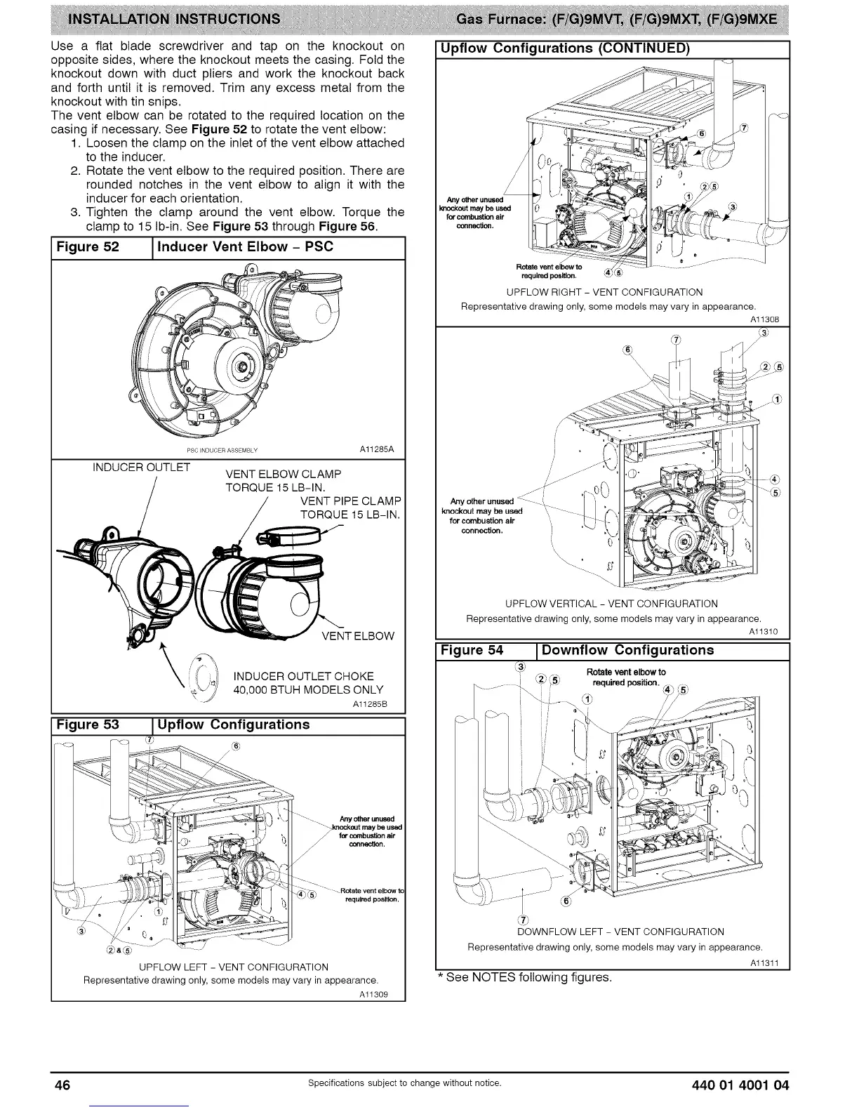
The vent elbow can be rotated to the required location on the
casing if necessary. See Figure 52 to rotate the vent elbow:
1. Loosen the clamp on the inlet of the vent elbow attached
to the inducer.
2. Rotate the vent elbow to the required position. There are
rounded notches in the vent elbow to align it with the
inducer for each orientation.
3. Tighten the clamp around the vent elbow. Torque the
clamp to 15 Ib-in. See Figure 53 through Figure 56.
Figure 52 I Inducer Vent Elbow - PSC
1
PSC INDUCER ASSEMBLY A11285A
INDUCER OUTLET
VENT ELBOW CLAMP
TORQUE 15 LB-IN.
VENT PIPE CLAMP
TORQUE 15 LB-IN.
Figure 53
\
VENT ELBOW
INDUCER OUTLET CHOKE
40,000 BTUH MODELSONLY
A11285B
Upflow Configurations
Any _ _'tused
for co_bustion air
o_nectten.
" - Rotate vent elbOW to
required position.
d2b_®
UPFLOW LEFT - VENT CONFIGURATION
Representative drawing only, some models may vary in appearance.
Al1309
Upflow Configurations (CONTINUED)
f/ ......
/ <[1=,; . o ......
=ot .........{
requim_l posi_on. _t:}'
UPFLOW RIGHT - VENT CONFIGURATION
Representative drawing only, some models may vary in appearance.
Alt308
_. (s)
_t m=ybe.=_ '., L / k_ ¢%
for combustion air ".... [ } {- ' _,_:_ _ ":_I"\
UPFLOW VERTICAL - VENT CONFIGURATION
Representative drawing only, some models may vary in appearancAi i310
Figure 54 Downflow Configurations
* See NOTES following figures.
Alt3tt
46 Specifications subject to change without notice. 440 01 4001 04