Figure 17 Exploded View of Base for
Downflow Cased Coil
25-21-46b
Subbase
Insulation
Setting the Base
Wood Floor
25 20 46A
This subbase for combustible floors has been designed so that
the height of the sub-base raises the downflow coil off the floor to
allow easy installation of the condensate drain. See Figure 19.
Non-Combustible Floor:
Set the furnace over the opening in the floor. If necessary, grout
around the base to seal air leaks between the base and the floor.
Figure 19 Condensate Line Raised by Base
25-20-52
Filters:
The filters supplied with the furnace may be installed in the return
air plenum above the furnace. A filter rack is supplied with each
downflow furnace. See Figure 20 and Figure 21.
NOTE: The furnace is provided with high velocity type filter(s).
The size, quantity, and type of filter supplied with the furnace will
handle the airflow required if central air conditioning is used with
the furnace.
NOTE: The return air plenum MUST extend a sufficient height
above dimension "A" (Figure 21 )to provide for the attachment of
a return air duct or grille above the filters.
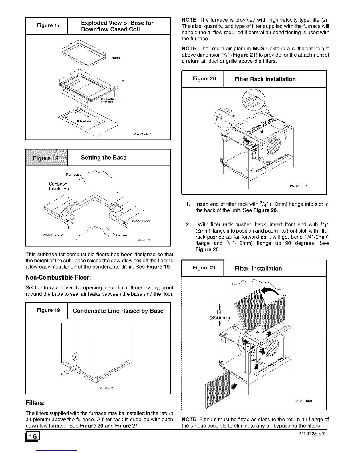
Figure20 Filter Rack Installation
t.
2,
25-21-05C
With filter rack pushed back, insert front end with 1/4"
(6mm) flange into position and push into front slot. with filter
rack pushed as far forward as it will go, bend 1/4"(6mm)
flange and 3/4"(19mm ) flange up 90 degrees. See
Figure 20.
Figure 21 Filter Installation
25-21-05d
NOTE: Plenum must be fitted as close to the return air flange of
the unit as possible to eliminate any air bypassing the filters.
44t 01230801
Insert end of filter rack with 3/4" (19mm) flange into slot in
the back of the unit. See Figure 20.

 Loading...