Filterscanonlybeinstalledthroughtherighthandsideof
theunitbloweropening.Slidefilterintounituntilitisinposi-
tiontobepushedupandoverintoplaceonthelefthand
sideofunit.SeeFigure21.
Slideremainingfilterintounitandupintoplaceonlefthand
sideofunit.SeeFigure21.
Ifthereisinsufficientplenumheightforthistypeofinstallation,fil-
tersmaybeinstalledinanyaccessiblelocationinthereturnair
system.Insuchacase,thefiltersshouldbeofequivalentsizeand
styleasoriginallysuppliedwiththefurnace.
Filter Removal
1. Remove compartment door.
2. Reach up above right side of blower and lift dirty filters out of
rack at top of furnace.
3. Straighten up filters and pull straight down at side of blower.
Pull out through right door opening.
4. Vacuum clean or wash with warm water and dry thoroughly
before replacing.
10. ChecksandAdjustments
Startup
NOTE: Refer to startup procedures in the Users Information
Manual.
CAUTION
If any sparks, odors or unusual noises occur, immedi-
ately shut OFF power to furnace, Check for wiring er-
rors or obstruction to blower,
GasSupplyPressure
Gas supply pressure should be within minimum and maximum
values listed on rating plate. Pressures are usually set by gas sup-
pliers.
(See L.P. Kit instruction manual for furnaces converted to L.R
gas)
ManifoldGas PressureAdjustment
NOTE: Make adjustment to manifold pressure with burners oper-
ating.
1.
2.
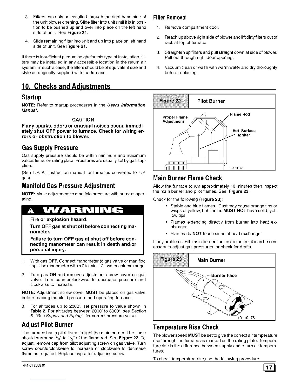
Pilot Burner
Flame Rod
Proper Flame _ /
_ / _"_ Hot Surface
10-11-65
MainBurner Flame Check
Allow the furnace to run approximately 10 minutes then inspect
the main burner and pilot flames. See Figure 23.
Check for the following (Figure 23):
Fire or explosion hazard.
Turn OFF gas at shut off before connecting ma-
nometer.
Failure to turn OFF gas at shut off before con-
• Stable and blue flames. Dust may cause orange tips or
wisps of yellow, but flames MUST NOT have solid, yel-
low tips.
• Flames extending directly from burner into heat ex-
changer.
• Flames do NOT touch sides of heat exchanger
necting manometer can result in death and/or
personal injury.
With gas OFF, Connect manometer to gas valve or maniflod
tap. Use manometer with a 0 to min. 12" water column range.
Turn gas ON and remove adjustment screw cover on gas
valve. Turn counterclockwise to decrease pressure and
clockwise to increase.
NOTE: Adjustment screw cover MUST be placed on gas valve
before reading manifold pressure and operating furnace.
3. For altitudes up to 2000', set pressure to value shown in
Table 2. For altitudes between 2000' to 8000', see Section
6. "Gas Supply and Piping" for correct pressure value.
Adjust PilotBurner
The furnace has a pilot flame to light the main burner. The flame
should surround 3/8" to 1/2" of the flame rod. See Figure 22. To
adjust, remove cap from pilot adjusting screw on gas valve. Turn
screw counterclockwise to increase or clockwise to decrease
flame as required. Replace cap after adjusting screw.
441 012308 01
If any problems with main burner flames are noted, it may be nec-
essary to adjust gas pressures, or check for drafts.
Main Burner
Burner Face
10-10-78
To check temperature rise,use the following procedure:
TemperatureRise Check
The blower speed MUST be set to give the correct air temperatu re
rise through the furnace as marked on the rating plate. Tempera-
ture rise is the difference between supply and return air tempera-
tures.

 Loading...