FIRE AND/OR EXPLOSION HAZARD
Failure to follow this warning could result in personal
injury, death, and/or property damage.
1. If the main burners fail to light, or the blower fails to
start, shut down gas heating section and call your
dealer for service.
2. Never attempt to manually light the main burners on
unit with a match, lighter, or any other flame. If the
electric sparking device fails to light the main burners,
refer to the following shutdown procedures, then call
your dealer as soon as possible.
TO SHUT UNIT OFF
FIRE AND/OR EXPLOSION HAZARD
Failure to follow this warning could result in personal
injury, death, and/or property damage.
Do not turn off the electrical power to unit without first
turning off the gas supply.
NOTE: If unit is being shut down because the heating
season has ended, make sure to turn on power to cooling
system,
If unit is being shut down because of a malfunction, call
your dealer as soon as possible.
Should the gas supply fail to shut off or if overheating
occurs, shut off the manual gas valve to the unit before
shutting off the electrical supply.
Do not use this furnace if any part has been under water. A
flood-damaged furnace is extremely dangerous. Attempts
to use the furnace can result in fire or explosion. A qualified
service agency should be contacted to inspect the furnace
and to replace all gas controls, control system parts,
electrical parts that have been wet or the furnace if deemed
necessary.
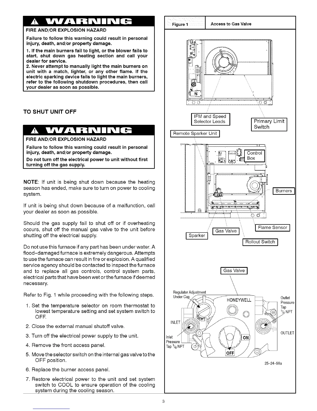
Refer to Fig. 1 while proceeding with the following steps.
1. Set the temperature selector on room thermostat to
lowest temperature setting and set system switch to
OFF.
2. Close the external manual shutoff valve.
3. Turn off the electrical power supply to the unit.
4. Remove the front access panel.
5. Move the selector switch on the internal gas valve to the
OFF position.
6. Replace the burner access panel.
7. Restore electrical power to the unit and set system
switch to COOL to ensure operation of the cooling
system during the cooling season.
FigUre i J Access to Gas Valve
O©
i ISelector Leads
IRemote Sparker Unit i
i Primary LimitSwitch I
',\
L
I__
Flame Sensor I
!
I GasValveI ''
I Rolleut Switch I
I Gas Valve ]
RegulatorAdjustment
UnderCa
,NL
Inlet
Pressure
Tap 1/8 NPT
HONEYWELL
©o
Outlet
Pressure
Tap
1/sNPT
J
OUTLET
25-24-98a