46201200402 9
Specifications are subject to change without notice.
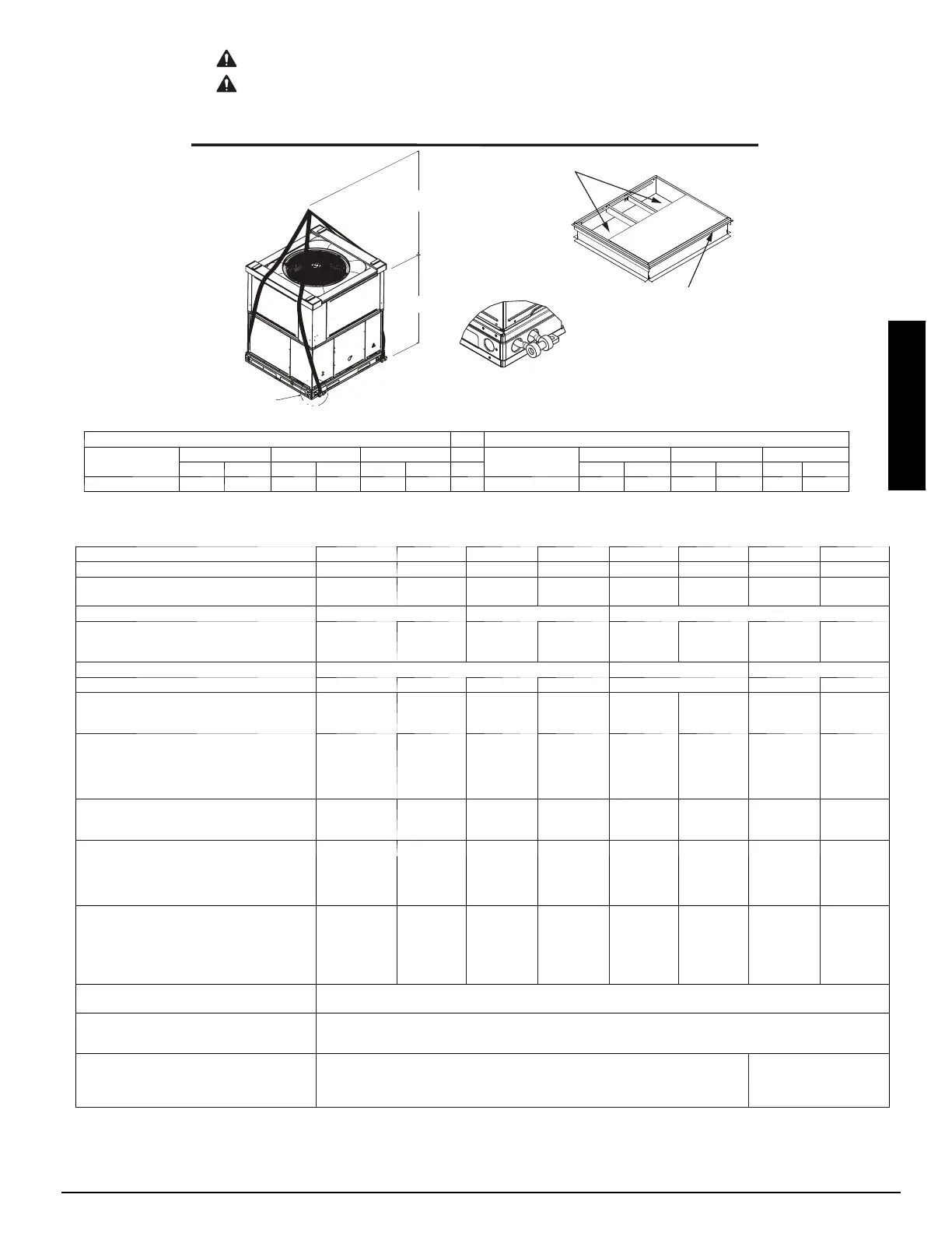
ACCESS PANELS MUST BE IN PLACE WHEN RIGGING.
PANNEAUX D'ACCES DOIT ÊTRE EN PLACE POUR MANIPULATION.
50CY502286 2.0
CAUTION - NOTICE TO RIGGERS
PRUDENCE - AVIS AUX MANIPULATEUR
Use top skid as spreader bar. / Utiliser la palette du haut comme barre de répartition
SEAL STRIP MUST BE IN
PLACE BEFORE PLACING
UNIT ON ROOF CURB
DUCTS
DETAIL A
VOIR DÉTAIL A
MINIMUM HEIGHT: 36" (914.4 mm)
HAUTEUR MINIMUM
UNIT HEIGHT
HAUTEUR D'UNITÉ
SEE DETAIL A
VOIR DÉTAIL A
BANDE SCELLANT DOIT ÊTRE
EN PLACE AVANT DE PLACER
L'UNITÉ SUR LA BASE DE TOIT
A09051
SMALL CABINET LARGE CABINET
Unit
24 30 36
Unit
42 48 60
lb kg lb kg lb kg lb kg lb kg lb kg
Rigging Weight 329 149 361 164 390 177 Rigging Weight 455 206 480 218 497 225
NOTE: See dimensional drawing for corner weights.
Fig. 8 -- Unit Suggested Rigging
Table 1 – Physical Data
UNIT SIZE 24040 24060 30040 30060 36060 36090 42060 42090
NOMINAL CAPACITY (ton) 2 2 2 --- 1 / 2 2 --- 1 / 2 3 3 3 --- 1 / 2 3 --- 1 /2
SHIPPING WEIGHT lb.
SHIPPING WEIGHT (kg)
329
149
329
149
361
164
361
164
390
177
390
177
455
206
455
206
COMPRESSOR / QUANTITY Rotary / 1 Recip / 1 Scroll / 1
REFRIGERANT (R --- 410A)
Quantity lb.
Quantity (kg)
5.3
2.4
5.3
2.4
5.5
2.5
5.5
2.5
8.2
3.7
8.2
3.7
6.2
2.8
6.2
2.8
REFRIGERANT METERING DEVICE Orifice TXV Orifice
ORIFICE ID in. / mm .059 / 1.5 .059 / 1.5 .061 / 1.55 .061 / 1.55 N/A .073 / 1.85 .073 / 1.85
OUTDOOR COIL
Rows...Fins/in.
Face Area (sq ft)
1..21
11.9
1...21
11.9
1...21
13.6
1...21
13.6
1...21
18.8
1...21
18.8
1...21
13.6
1...21
13.6
OUTDOOR FAN
Nominal CFM
Diameter in.
Diameter (mm)
Motor Hp (Rpm)
2500
24
609.6
1/10 (810)
2500
24
609.6
1/10 (810)
2700
24
609.6
1/10 (810)
2700
24
609.6
1/10 (810)
3200
24
609.6
1/5 (810)
3200
24
609.6
1/5 (810)
3600
26
660.4
1/5 (810
3600
26
660.4
1/5 (810)
INDOOR COIL
Rows...Fins/in.
Face Area (sq ft)
3...17
3.7
3...17
3.7
3...17
3.7
3...17
3.7
3...17
3.7
3...17
3.7
3...17
4.7
3...17
4.7
INDOOR BLOWER
Nominal C ooling Airflow (Cfm)
Size in.
Size (mm.)
Motor HP (RPM)
800
10x10
254x254
1/2 (1050)
800
10x10
254x254
1/2 (1050)
1000
10x10
254x254
1/2 (1050)
1000
10x10
254x254
1/2 (1050)
1150
11x10
279.4x254
3/4 (1000)
1150
11x10
279.4x254
3/4 (1000)
1350
11x10
279.4x254
3/4 (1075)
1350
11x10
279.4x254
3/4 (1075)
FURNACE SECTION*
Burner Orifice No. (Qty...Drill Size)
1 Phase Natural Gas (Factory Installed)
1 Phase Propane Gas
3 Phase Natural Gas (Factory Installed)
3 Phase Propane Gas
2...44
2...55
3...44
3...55
2...44
2...55
2...44
2...55
3...44
3...55
2...38
2...53
3...44
3...55
2...38
2...53
3...38
3...53
3...38
3...53
3...44
3...55
2...38
2...53
3...38
3...53
3...38
3...53
HIGH --- PRESSURE SWITCH
(psig) Cut---out Reset (Auto)
650 +/-- 15
420 +/-- 25
LOSS--OF--CHARGE / LOW--PRESSURE
SWITCH (Liquid Line) (psig) cut--out Reset
(auto)
20 +/-- 5
45 +/-- 10
RETURN ---AIR FILTERS†}
Throwaway Size in.
(mm)
2 ea ch 20x12x1
508x305x25
1 ea ch 24x14x1
610x356x25
24x15x1
610x406x25
*Based on altitude of 0 to 2000 ft ( 0 ---610 m).
{ Required filter sizes shown are based on the larger of the AHRI (Air Conditioning Heating and Refrigeration Institute) rated cooling airflow or the heating air-
flow velocity of 300 to 350 ft/minute for throwaway type. Air filter pressure drop f or non ---standard filters mu st not exceed 0.08 IN. W.C.
} If using accessory filter rack refer to the filter rack installation instructions for correct filter sizes and quantity.
PGD4, PGS4, WPG4