10 46201200402
Specifications are subject to change without notice.
Table 1—Physical Data Con’t
UNIT SIZE 48090 48115 48130 60090 60115 60130
NOMINAL CAPACITY (ton) 4 4 4 5 5 5
SHIPPING WEIGHT lb
SHIPPING WEIGHT kg
480
218
480
218
480
218
497
225
497
225
497
225
COMPRESSOR / QUANTITY Scroll / 1
REFRIGERANT (R --- 410A)
Quantity lb
Quantity (kg.)
9.2
4.2
9.2
4.2
9.2
4.2
9.8
4.4
9.8
4.4
9.8
4.4
REFRIGERANT METERING DEVICE Orifice
ORIFICE ID in./mm .080 / 2.03 .084 / 2.14
OUTDOOR COIL
Rows...Fins/in.
Face Area (sq ft)
1...21
21.4
1...21
21.4
1...21
21.4
1...21
23.3
1...21
23.3
1...21
23.3
OUTDOOR FAN
Nominal Cfm
Diameter in.
Diameter (mm)
Motor Hp (Rpm)
3600
26
660.4
1/5 (810)
3600
26
660.4
1/5 (810)
3600
26
660.4
1/5 (810)
4200
26
660.4
1/5 (810)
4200
26
660.4
1/5 (810)
4200
26
660.4
1/5 (810)
INDOOR COIL
Rows...Fins/in.
Face Area (sq ft)
3...17
4.7
3...17
4.7
3...17
4.7
3...17
5.6
3...17
5.6
3...17
5.6
INDOOR BLOWER
Nominal C ooling Airflow (Cfm)
Size in.
Size (mm)
Motor HP (RPM)
1550
11x10
279.4x254
1.0 ( 1075)
1550
11x10
279.4x254
1.0 ( 1075)
1550
11x10
279.4x254
1.0 ( 1075)
1750
11x10
279.4x254
1.0 ( 1040)
1750
11x10
279.4x254
1.0 ( 1040)
1750
11x10
279.4x254
1.0 ( 1040)
FURNACE SECTION*
Burner Orifice No. (Qty ...Drill Size)
1 & 3 Phase Natural Gas (Factory Installed)
1&3PhasePropaneGas
3...38
3...53
3...33
3...51
3...31
3...49
3...38
3...53
3...33
3...51
3...31
3...49
HIGH --- PRESSURE SWITCH
(psig) Cut---out Reset (Auto)
650 +/ --- 15
420 +/ --- 25
L O S S --- O F C H A R G E / L O W --- P R E S S U R E
SWITCH (Liquid Line) (psig) cut--- out Reset
(auto)
2 0 + / --- 5
45 +/ --- 10
N/A
RETURN ---AIR FILTERS Throwaway†} in.
mm
1 ea ch 24x14x1
610x356x25
24x15x1
610x406x25
1 ea ch 24x16x1
610x406x25
24x18x1
610x457x25
*Based on altitude of 0 to 2000 ft ( 0 ---610 m).
{ Required filter sizes shown are based on the larger of the AHRI (Air Conditioning Heating and Refrigeration Institute) rated cooling airflow or the heating air-
flow velocity of 300 to 350 ft/minute for throwaway type. Air filter pressure drop f or non ---standard filters mu st not exceed 0.08 IN. W.C.
} If using accessory filter rack refer to the filter rack installation instructions for correct filter sizes and quantity.
Table 2 – Maximum Gas Flow Capacity*
NOMINAL
IRON PIPE
SIZE (IN.)
INTERNAL
DIAMETER
(IN.)
LENGTH OF PIPE FT (m)†
10
(3)
20
(6)
30
(9)
40
(12)
50
(15)
60
(18)
70
(21)
80
(24)
90
(27)
100
(30)
125
(38)
150
(46)
175
(53)
200
(61)
1/2 .622 175 120 97 82 73 66 61 57 53 50 44 40 — —
3/4 .824 360 250 200 170 151 138 125 118 110 103 93 84 77 72
1 1.049 680 465 375 320 285 260 240 220 205 195 175 160 145 135
1 --- 1 / 4 1.380 1400 950 770 600 580 530 490 460 430 400 360 325 300 280
1 --- 1 / 2 1.610 2100 1460 1180 990 900 810 750 690 650 620 550 500 460 430
*Capacity of pipe in cu ft of gas per hr for gas pressure of 0.5 psig or less. Pressure drop of 0.5 ---IN. W.C. (based on a 0.60 specific gravity gas). Refer toTable2
and National Fuel Gas Code NFPA 54/ANSI Z223.1.
{ This length includes an ordinary number of fittings.
Step 6 — Connect Condensate Drain
NOTE: When installing condensate drain connection be sure to
comply with local codes and restrictions.
This unit disposes of condensate water through a 3/4 in. NPT
fitting which exits through the base on the evaporator coil access
side. See Fig. 3--6 for location.
Condensate water can be drained directly onto the roof in rooftop
installations (where permitted) or onto a gravel apron in ground
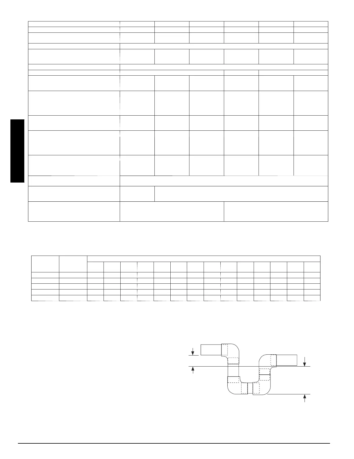
level installations. Install a field--supplied 2--in. (51 mm)
condensate trap at the end of condensate connection to ensure
proper drainage. Make sure that the outlet of the trap is at least 1 in.
(25 mm) lower than the drain --pan condensate connection to
prevent the pan from overflowing (See Fig. 9). Prime the trap with
water. When using a gravel apron, make sure it slopes away from
the unit.
Connect a drain tube using a minimum of 3/4--in. PVC or 3/4--in.
copper pipe (all field--supplied) at the outlet end of the 2--in. (51
mm) trap. Do not undersize the tube. Pitch the drain tube
downward at a slope of at least 1--in. (25 mm) for every 10 ft (3.1
m) of horizontal run. Be sure to check the drain tube for leaks.
TRAP
OUTLET
1-in. (25 mm) min.
2-in. (51 mm) min.
A09052
Fig. 9 -- Condensate Trap
PGD4, PGS4, WPG4