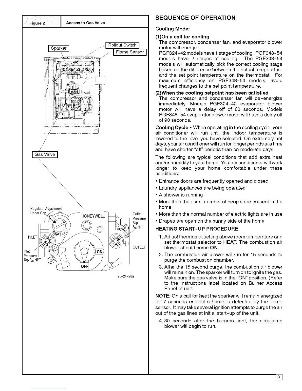
F gure 2 1 Access to Gas Valve
..... I Rollout Switch I
Sparker J ........I I
-- _............ ..............I Flame Sensor I
i
1
I'1
t
I Gas Valve ]
Regu
Under Ca
,NL
Inlet
Pressure
Tap1/8NPT
HONEYWELL
©
Outlet
Pressure
Tap
1/8NPT
J
OUTLET
25-24-98a
SEQUENCE OF OPERATION
Cooling Mode:
(1)On a call for cooling
The compressor, condenser fan, and evaporator blower
motor will energize.
PGF324-42 models have 1stage of cooling. PGF348-54
models have 2 stages of cooling. The PGF348-54
models will automatically pick the correct cooling stage
based on the difference between the actual temperature
and the set point temperature on the thermostat. For
maximum efficiency on PGF348-54 models, avoid
frequent changes to the set point temperature.
(2)When the cooling setpoint has been satisfied
The compressor and condenser fan will de-energize
immediately. Models PGF324-42 evaporator blower
motor will have a delay off of 60 seconds. Models
PGF348-54 evaporator blower motor will have a delay off
of 90 seconds.
Cooling Cycle - When operating in the cooling cycle, your
air conditioner will run until the indoor temperature is
lowered to the level you have selected. On extremely hot
days, your air conditioner will run for longer periods at a time
and have shorter "off' periods than on moderate days.
The following are typical conditions that add extra heat
and/or humidity to your home. Your air conditioner will work
longer to keep your home comfortable under these
conditions:
• Entrance doors are frequently opened and closed
• Laundry appliances are being operated
• A shower is running
• More than the usual number of people are present in the
home
• More than the normal number of electric lights are in use
• Drapes are open on the sunny side of the home
HEATING START-UP PROCEDURE
1. Adjust thermostat setting above room temperature and
set thermostat selector to HEAT. The combustion air
blower should come ON.
2,
3.
The combustion air blower wil run for 15 seconds to
purge the combustion chamber.
After the 15 second purge, the combustion air blower
will remain on. The sparker will turn on to ignite the gas.
Make sure the gas valve is in the "ON" position. (Refer
to the instructions label located on Burner Access
Panel of unit.
NOTE: On a call for heat the sparker will remain energized
for 7 seconds or until a flame is detected by the flame
sensor. It may take several ignition attempts to purge the air
out of the gas lines at initial start-up of the unit.
4.30 seconds after the burners light, the circulating
blower will begin to run.
131