6. Wire Diagrams
2-31/2 Ton Models
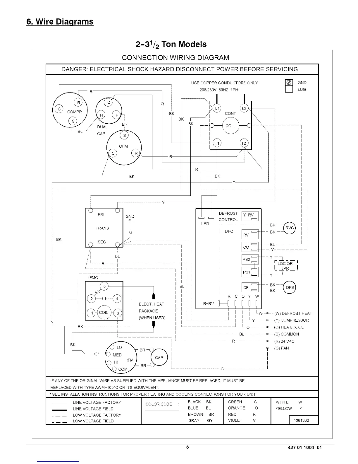
CONNECTION WIRING DIAGRAM
DANGER: ELECTRICAL SHOCK HAZARD DISCONNECT POWER BEFORE SERVICING
DUAL
EK
BK
USE COPPER CONDUCTORS ONLY
208/230V 60HZ 1PH
_ CONT
BK
B ND
LUG
CAP
BK
4-
BK
PRt
TRANS
SEC
I
BL
I...........R I
I
ELECT. HEAT
PACKAGE
(WHEN USED)
I IFMC
I
Ltc 3b
BK I
I
I
BR
I
I
I
I
_q
DEFROST
CONTROL
FAN
BK
<*
DEC
BL
Y
Yr&---i
LOC OR
L_P___!
y •
R C
R-RV
I
I I
I
I
L _ J
I
O Y W
I I Lw+_ (w) DEFROST HEAT
I
I L y (y) COMPRESSOR
L O -------e--(O) HEAT/COOL
BL .... -e-- (C) COMMON
R e- (R) 24 VAC
(G) FAN
I
I
I
...............................................................................................G •
tF ANY OF THE ORIGINAL WIRE AS SUPPLIED WITH THE APPLIANCE MUST BE REPLACED, IT MUST BE
A
REPLACED WITH TYPE AWM-105 C OR ITS EQUIVALENT.
* SEE INSTALLATION INSTRUCTIONS FOR PROPER HEATING AND COOLING CONNECTIONS FOR YOUR UNIT
LINE VOLTAGE FACTORY COLOR CODE : BLACK BK GREEN G
/ LINE VOLTAGE FIELD BLUE BL ORANGE O
LOW VOLTAGE FACTORY BROWN BR RED R
= i i LOW VOLTAGE FIELD GRAY GY VIOLET V
WHITE W
YELLOW Y
6 427 01 1004 01
 Loading...