OPERATING AND MAINTENANCE MANUAL
Chapter 4 - Description
iC 215 ÷ iC 780
21
The data in this manual are not binding and they can be modified by the manufacturer without notice. Reproduction of this manual is strictly prohibited
EN
ENGLISH
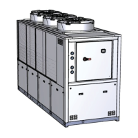
4.7.2 Axial for /HE version (only on high efficiency models, where envisaged)
The /HE version is fitted with extremely low noise, high efficiency fans, with integral inverter motor and EC technology
(with permanent magnets and electronic switching).
4.7.3 High pressure axial flow fans
These fans are supplied optionally and can be installed exclusively on models iC 520÷780. The fans are high pressure units
with an integral bell mouth made of composite material and inverter type electronic speed control.
4.7.4 Centrifugal
Centrifugal fans are supplied optionally and can be fitted to iC 303÷416 models.
These are double acting fans with the fanwheel coupled directly to the motor shaft and they feature ON/OFF control.
The fans outlet port is located on the top of the unit.
The centrifugal fans feature ON/OFF control for iC 303÷305 and STEP control for iC 408÷416.
4.8 Cabinet
The entire plinth, the uprights, and the outer panels are made of galvanized carbon steel sheet and are assembled by means of
screws and/or rivets. All panels undergo phosphor degreasing treatment followed by epoxy polyester power coating.
The frame is designed to allow easy access to all components of the unit.
4.9 Materials in contact with the liquid to be cooled
Standard chillers: carbon steel, copper, aluminium, zinc, brass, stainless steel and plastic materials
specifically:
• evaporator with copper tubes, aluminium fins and galvanized sheet metal shoulders;
• carbon steel tank.
Chillers with non-ferrous hydraulic circuit (iC 215÷540): stainless steel (AISI 304), copper, brass and plastic materials.
Specifically:
• with copper tubes and fins and brass shoulders;
• tank in AISI 304 stainless steel.
Alternatively
• external plate evaporator;
• tank in AISI 304 stainless steel.
The pump mechanical seals are in silicon carbide/silicon carbide/EPDM.
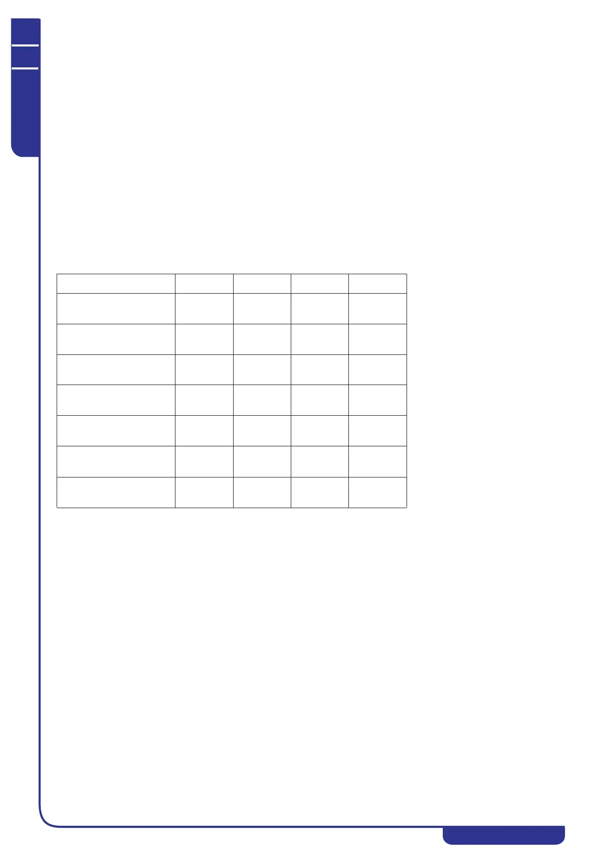
4.10 Overall dimensions and minimum clearances with
respect to walls
See the enclosed electrical diagrams.
4.11 Electrical circuit
Refer to Chapter 5 “Installation” for information on electrical hook-ups and consult the attached diagrams.
Model Width Depth Height
iC 215÷220
(mm)
(in)
560
22
1265
49.8
794
31.2
iC 303÷305
(mm)
(in)
660
26
1310
51.6
1400
55.1
iC 408÷416
(mm)
(in)
760
29.9
1865
73.4
1447
57
iC 520÷535
(mm)
(in)
865
34
2255
88.8
2065
81.3
iC 538÷540
(mm)
(in)
1150
45.2
2790
110
2091
82.3
iC 640÷660
(mm)
(in)
1255
49.4
3295
129.7
2140
84.2
iC 770÷780
(mm)
(in)
1251
49.2
3350
131.9
2153
84.7