15
icos - Installation & Servicing
INSTALLATION
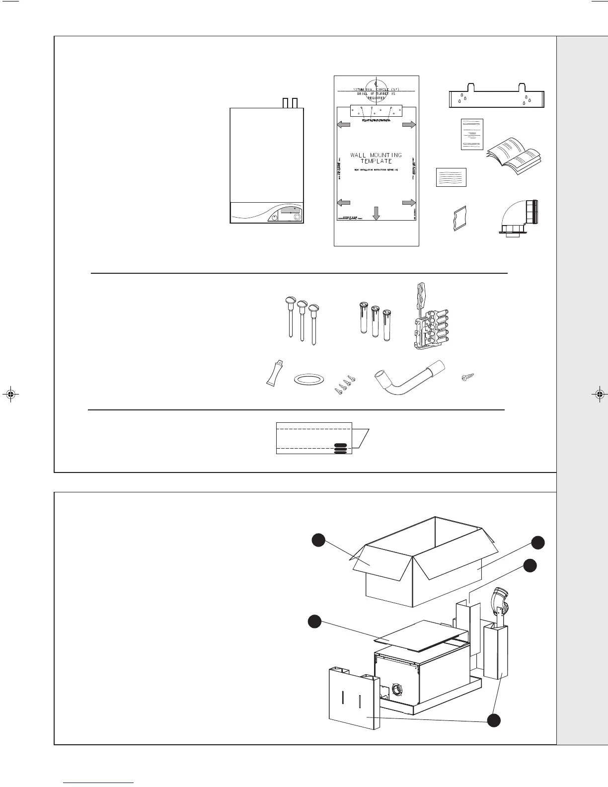
The boiler is supplied fully assembled in one Pack A,
together with a standard flue assembly for lengths up to
650mm, rear or side flue outlet, in Pack B.
Unpack and check the contents.
11
UNPACKING
Hardware Pack
A 50mm x No.14 wood screws - 3 off
B Wall plugs (TP2B ) - 3 off
C Mains connector - 1 off
D Lubricant - 1 off
E Turret Sealing Gasket - 1 off
F Turret Fixing Screws - 4 off
G Condensate Tube - 1 off
H No. 8 x 10 boiler fixing screw - 1 off
Pack A Contents
A The boiler
B Wall mounting template
C Wall mounting plate
D 1 year guarantee form
E These Installation & Servicing/
User’s Instructions
F Water Treatment Warning Label
G Hardware pack
H Flue Turret
Pack B Contents
Flue terminal
1. Ensure the boiler is stood correctly, as marked on the
carton.
2. Cut and remove the strapping.
3. Fold back the top flaps to gain access to the wall
mounting plate, literature and wall mounting
template.
4. Remove the instructions and read thoroughly before
unpacking the product.
5. Remove the hardware pack and keep in a safe
place.
6. When ready for installation lift off the outer sleeve.
7. Remove the top protection packing.
8. Remove the two packaging ends.
12
PACKAGING REMOVAL
mxhe7658
nm8231
5
6
3
7
8
INSTALLATION
202414-6.pmd 19/02/2008, 13:0715