16
icos - Installation & Servicing
INSTALLATION
225 225
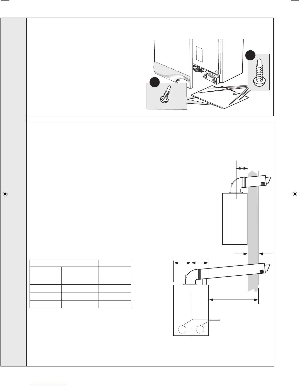
Rear flue length X
Side flue length L
Jacking screws
nm8115
137
13
FRONT AND BOTTOM PANEL REMOVAL
IMPORTANT. The boiler MUST be installed in a vertical position
Dimension X - Wall thickness.
Dimension L - Wall thickness plus boiler spacing.
1. To remove the front panel remove the 4 screws from the
bottom panel.
2. Lift the panel up and off the top pegs.
3. To remove the bottom panel remove the 4 screws and
withdraw.
14
DETERMINING THE FLUE LENGTH AND FLUE PACKS REQUIRED
FLUE KITS
Pack B - supplied as standard
For additional fluing options refer to OPTIONAL EXTRA KITS on page 7.
MAXIMUM FLUE LENGTHS:
HORIZONTAL FLUE - 3M
ROOF FLUE KIT - 5M
90
O
ELBOW KIT 60/100 (EQUIVALENT FLUE LENGTH RESISTANCE = 1.5M)
45
O
ELBOW KIT 60/100 (EQUIVALENT FLUE LENGTH RESISTANCE = 1.0M)
MINIMUM FLUE LENGTH:
FOR REAR OUTLET AND SINGLE BRICK WALL - 251MM
Notes.
1. The flue duct MUST be inclined at 1.5 degrees to the horizontal to allow condensate to drain back into the boiler and out
through the condensate drain. (Only necessary if using one or more ‘D’ extension duct packs).
2. If the boiler is to be installed with downward piping routed behind the boiler then the optional stand-off kit should be used.
Care must be taken when cutting the ducts and marking the wall to suit this condition.
Total Flue length dimension Flue
Rear flue Side flue Extra packs
dim. X+137 dim. L+225 required
Up to 775 mm Up to 775 mm none
Up to 1680 mm Up to 1680 mm Pack D - 1 off
Up to 2585 mm Up to 2585 mm Pack D - 2 off
Up to 3000 mm Up to 3000 mm Pack D - 3 off
INSTALLATION
202414-6.pmd 19/02/2008, 13:0716