Note. Fit the earth strap provided with the PCB to your
wrist and a suitable earth on the boiler chassis.
1. Refer to Frame 40.
2. Remove the main PCB, refer to Frame 51.
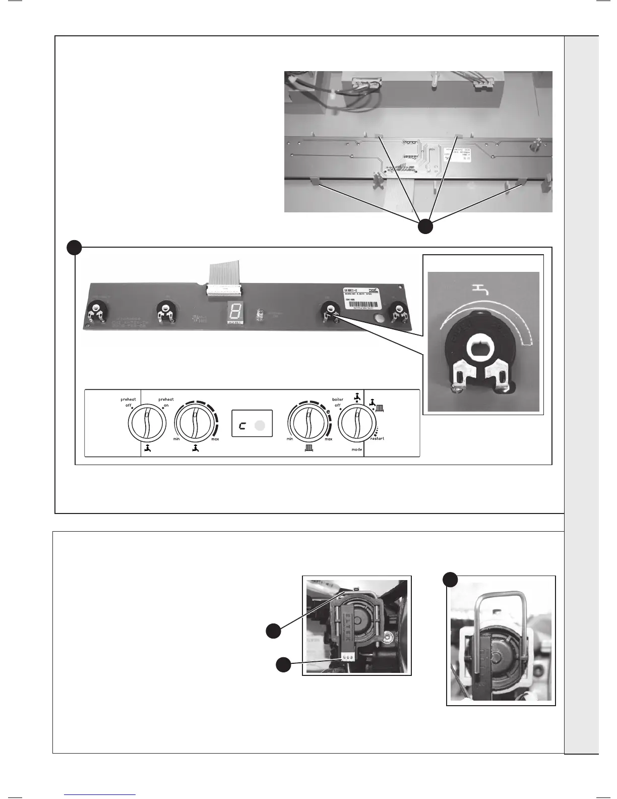
3. Unclip the PCB and lift to clear the mounting posts.
4. Fit the new PCB ensuring the 4 potentiometer
spindles line up with the control knobs which must
be in a vertical position.
5. Reassemble in reverse order.
6. Check operation of the boiler. Refer to Frames 29 &
30.
52
USER CONTROL PCB REPLACEMENT
3
Potentiometer spindle
Control Knobs (to be in vertical position)
PCB
4
56
DHW FLOW TURBINE SENSOR REPLACEMENT
1. Refer to Frame 40.
2. Drain the DHW system. Refer to Frame 54.
3. Pull off the electrical connection.
4. Using a suitable tool, lift and remove the
retaining clip.
5. Use the clip to ease the turbine sensor from its
housing.
6. Re-assemble in reverse order.
7. Check operation of the boiler. Refer to Frame
29 & 30.
4
3
5
SERVICING



 To Next Page