INSTALLATION
mini HE --- Installation & Servicing
17
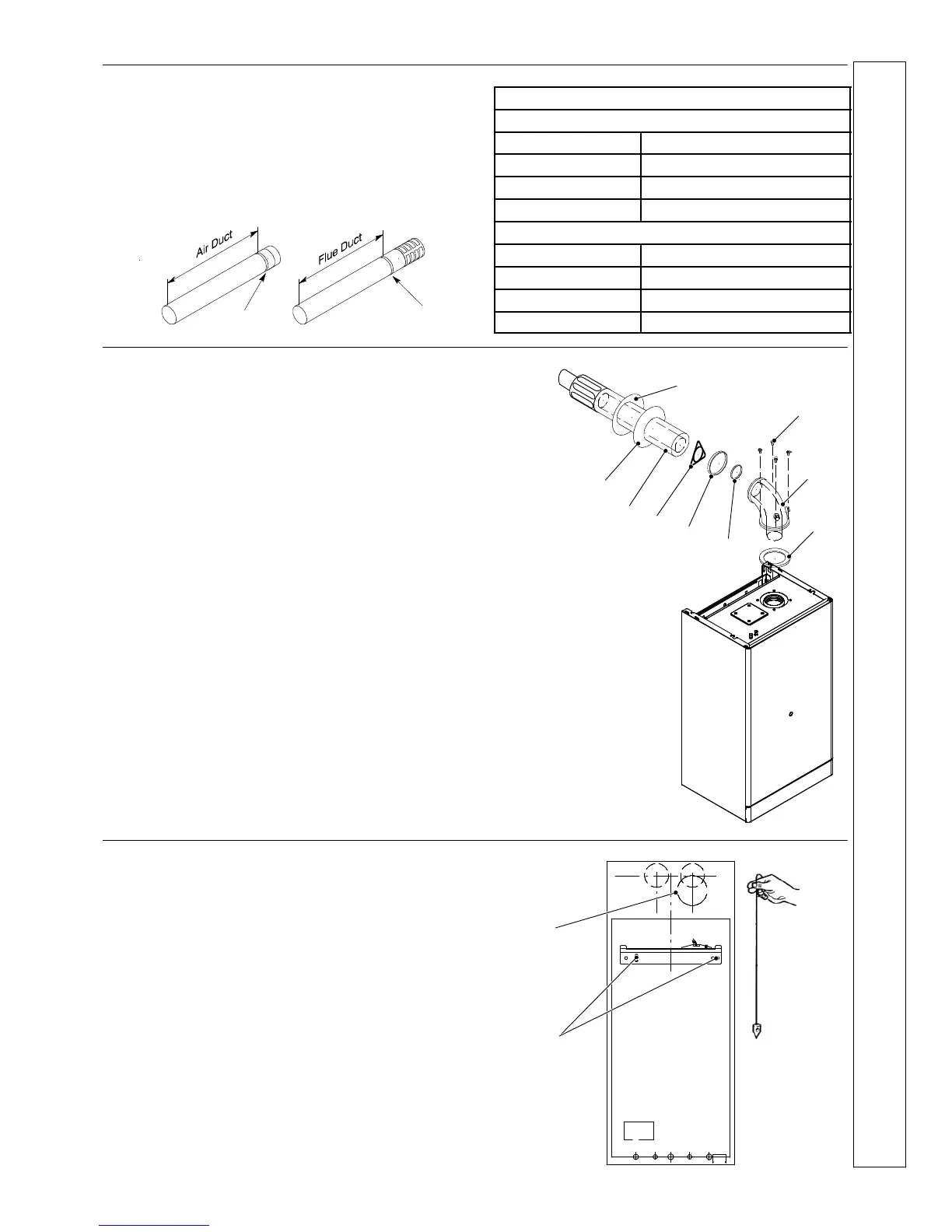
Cutting lengths of flue and air ducts
Measure the wall thickness and, when using a side outlet, the
gap between the inner wall and the boiler side casing. Use
the following chart to calculate the cutting lengths of both flue
and air ducts.
Mark the air duct and flue duct making reference on the
groove.
Groove
Groove
Twin Pipe
Air duct
Rear Outlet Wall thickness + 130 mm
Rear outlet+Stand---off Wall thickness + 165 mm
Side Outlet --- RH Wall thickness + Gap + 187 mm
Side Outlet --- LH Wall thickness + Gap + 93 mm
Flue Duct
Rear Outlet Wall thickness + 130 mm
Rear outlet+Stand---off Wall thickness + 165 mm
Side Outlet --- RH Wall thickness + Gap +67 mm
Side Outlet --- LH Wall thickness + Gap + 213 mm
12 REAR FLUE ASSEMBLY
Legend
1 Wall finishing gasket --- external (rubber)
2 Self tapping screw 4,2x13
3 Flue turret
4 Boiler---turret gasket
5 Flue pipe gasket
6 Turret---air pipe gasket
7 Centring spring
8 Air/flue pipe with terminal grille assembly
9 Wall finishing gasket --- internal (plastic)
1
8
9
7
6
5
4
3
2
13 WALL MOUNTING TEMPLATE
(rear flue)
IMPORTANT
Detailed installation steps are given directly on the wall
mounting template
1 Tape the template into the selected position.
2 Ensure squareness by hanging a plumbine.
3 Mark onto the wall the following:
a. the wall mounting plate screw positions
b. the position of the flue duct.
(Mark the centre of the hole as well as the circumference)
4 Remove the template from the wall
a
b
INSTALLATION
 Loading...